Communication Processor Module
MOTOROLA MPC823e REFERENCE MANUAL 16-510
CPIC
COMMUNICATION
16
PROCESSOR MODULE
16.15.5.4 CPM INTERRUPT IN-SERVICE REGISTER. Each bit in the 32-bit read/write
CPM interrupt in-service register (CISR) corresponds to a CPM interrupt source. In a
vectored interrupt environment, the CPM interrupt controller sets the CISR bit when the core
acknowledges the interrupt by setting the IACK bit in the CPM interrupt vector register. Your
interrupt service routine must clear this bit after servicing is complete. If an event register
exists for this peripheral, its bits would normally be cleared as well. To clear a bit in the CISR,
write a 1 to that bit. Since you can only clear bits in this register, bits written as zeros will not
be affected. The CISR is cleared by reset.
You can read this register to determine the interrupt requests that are currently in progress
for each CPM interrupt source. More than one bit in the CISR can be a 1 if higher priority
CPM interrupts are allowed to interrupt lower priority level interrupts within the same CPM
interrupt level. For example, the TIMER1 interrupt routine could interrupt the handling of the
TIMER2 routine using a special nesting technique described earlier. During this time, you
can see both the TIMER2 and the TIMER1 bits simultaneously set in the CISR.
Note: The USB or SCCx CIMR bit positions are unaffected by the relative priority
between the USB or SCCs. To clear bits that were set by multiple interrupt events,
you must clear all the unmasked events in the corresponding event register. If a
bit in the CIMR is masked at the same time that the corresponding CIPR bit
causes an interrupt request to the core, then the interrupt is not processed, but
the error vector is issued if the interrupt acknowledge cycle occurs with no other
CPM interrupts pending. Thus, you must always include an error vector routine,
even if it just contains the rfi instruction. The error vector cannot be masked.
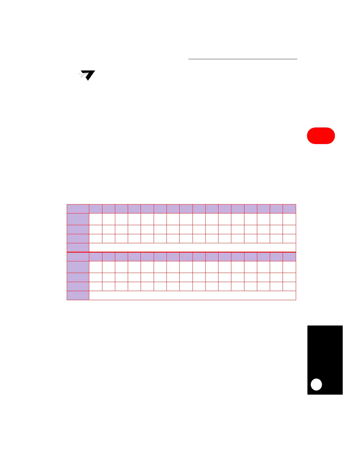
CISR
BIT 0 1 2 3 4 5 6 7 8 9 10 11 12 13 14 15
FIELD
PC15 USB SCC2 SCC3 RES PC14
TIMER
1
PC13 PC12 SDMA IDMA1 IDMA2 RES
TIMER
2
R–TT I2C
RESET
0000000000000000
R/W
R/W R/W R/W R/W R/W R/W R/W R/W R/W R/W R/W R/W R/W R/W R/W R/W
ADDR
(IMMR & 0xFFFF0000) + 0x94C
BIT 16 17 18 19 20 21 22 23 24 25 26 27 28 29 30 31
FIELD
PC11 PC10 RES
TIMER
3
PC9 PC8 PC7 RES
TIMER
4
PC6 SPI SMC1 SMC2 PC5 PC4 RES
RESET
0000000000000000
R/W
R/W R/W R/W R/W R/W R/W R/W R/W R/W R/W R/W R/W R/W R/W R/W R/W
ADDR
(IMMR & 0xFFFF0000) + 0x94E
 Loading...

