Communication Processor Module
16-509 MPC823e REFERENCE MANUAL MOTOROLA
CPIC
COMMUNICATION
16
PROCESSOR MODULE
In a polled interrupt scheme, you must periodically read the CIPR. When a pending interrupt
is handled, clear the corresponding bit in the CIPR. However, if an event register exists,
clear the unmasked event register bits instead, thus causing the CIPR bit to be cleared. To
clear a bit in the CIPR, write a 1 to that bit. Since you can only clear bits in this register, bits
written as zeros are unaffected. The CIPR is cleared at reset.
16.15.5.3 CPM INTERRUPT MASK REGISTER. Each bit in the 32-bit read/write CPM
interrupt mask register (CIMR) corresponds to a CPM interrupt source. You can mask an
interrupt by clearing the corresponding bit in the CIMR and you can enable one by setting
the corresponding bit in the CIMR. When a masked CPM interrupt occurs, the corresponding
bit in the CIPR is still set, regardless of the CIMR bit, but no interrupt request is passed to
the core.
If a CPM interrupt source is requesting interrupt service when you clear its corresponding
bit in the CIMR, the request stops. If you set its bit in the CIMR later, a previously pending
interrupt request is processed by the core, according to its assigned priority. You can read
the CIMR at any time and it is cleared by reset.
Note: The USB or SCCx CIPR bit positions are not changed according to the relative
priority between the USB or SCCs (as determined by the SCxP and SPS bits in
the CICR). Writing a zero to a bit in the CIPR has no effect.
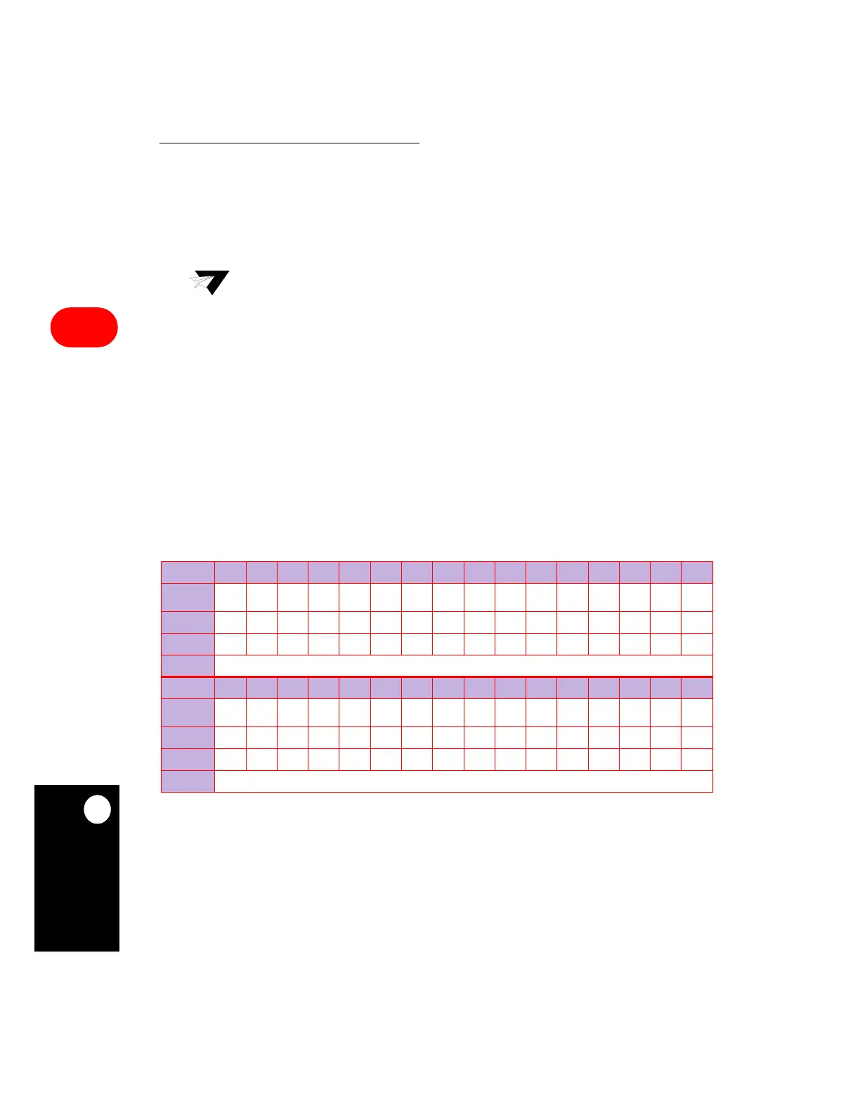
CIMR
BIT 0 1 2 3 4 5 6 7 8 9 10 11 12 13 14 15
FIELD
PC15 USB SCC2 SCC3 RES PC14
TIMER
1
PC13 PC12 SDMA IDMA1 IDMA2 RES
TIMER
2
R–TT I2C
RESET
0000000000000000
R/W
R/W R/W R/W R/W R/W R/W R/W R/W R/W R/W R/W R/W R/W R/W R/W R/W
ADDR
(IMMR & 0xFFFF0000) + 0x948
BIT 16 17 18 19 20 21 22 23 24 25 26 27 28 29 30 31
FIELD
PC11 PC10 RES
TIMER
3
PC9 PC8 PC7 RES
TIMER
4
PC6 SPI SMC1 SMC2 PC5 PC4 RES
RESET
0000000000000000
R/W
R/W R/W R/W R/W R/W R/W R/W R/W R/W R/W R/W R/W R/W R/W R/W R/W
ADDR
(IMMR & 0xFFFF0000) + 0x94A
 Loading...

