PCMCIA Interface
MOTOROLA
MPC823e REFERENCE MANUAL
17-9
PCMCIA INTERFACE
17
17.5 PROGRAMMING THE PCMCIA INTERFACE
The following section describes the PCMCIA interface programming model. All registers are
memory-mapped within the internal control register area. The following registers are used
to control the PCMCIA interface.
17.5.1 PCMCIA Interface Input Pins Register
The PCMCIA interface input pins register (PIPR) is used to sample the PCMCIA input port
signals. When the PCMCIA controller is not operating, bits 16-23 of the PIPR can be used
to read from and write to the IP_B[0:7] pins as general-purpose I/O pins.
Bits 0–15—Reserved
These bits are reserved and must be set to 0.
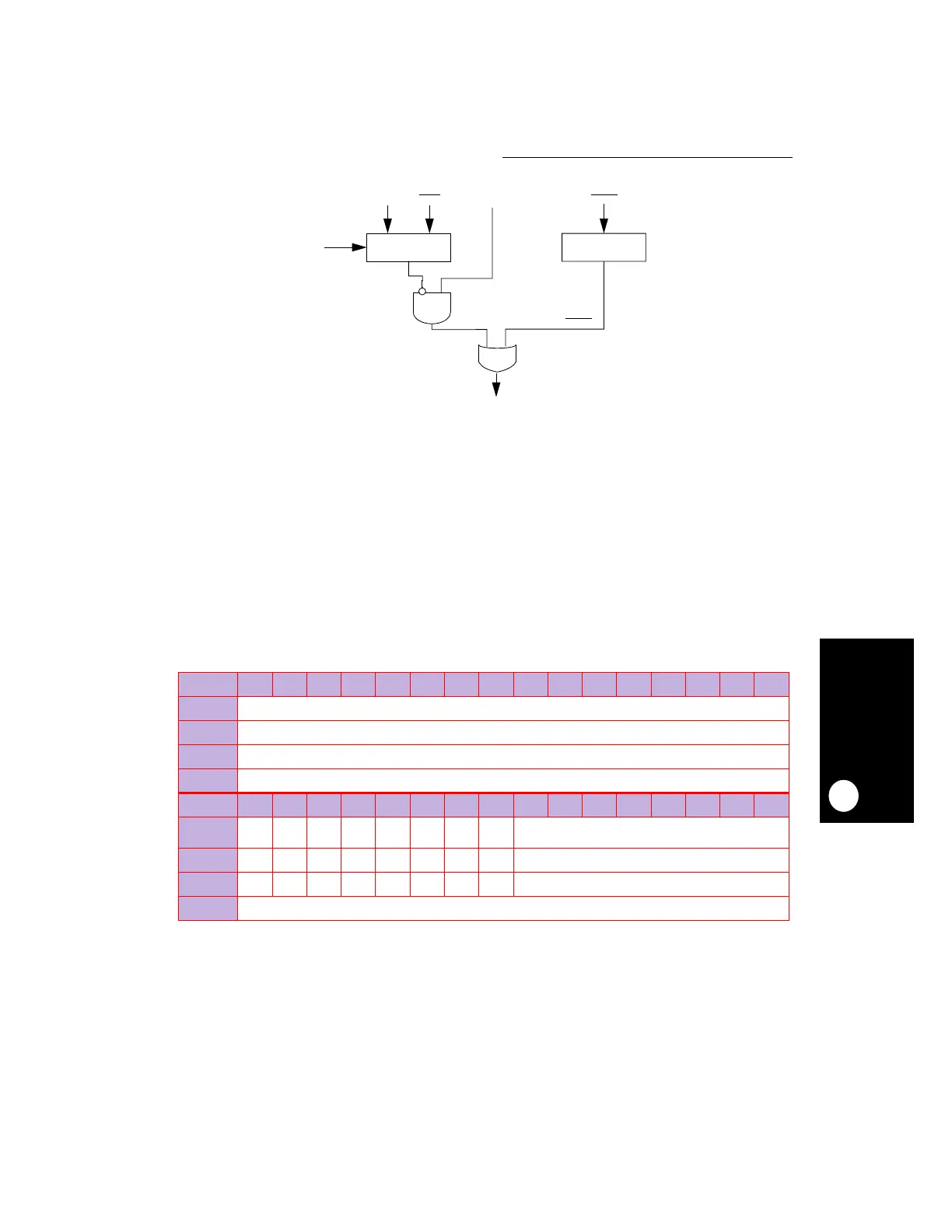
Figure 17-2. Internal DMA Request Logic
PIPR
BIT
0 1 2 3 4 5 6 7 8 9 10 11 12 13 14 15
FIELD
RESERVED
RESET
—
R/W
R/W
ADDR
(IMMR & 0xFFFF0000) + 0xF0
BIT
16 17 18 19 20 21 22 23 24 25 26 27 28 29 30 31
FIELD
CBVS1 CBVS2 CBWP CBCD2 CBCD1
CBBVD
2
CBBVD
1
CBRDY RESERVED
RESET
———————— —
R/W
R/W R/W R/W R/W R/W R/W R/W R/W R/W
ADDR
(IMMR & 0xFFFF0000) + 0xF0
NOTE: — = Undefined.
IOIS16_B SPKR DREQ2CBDREQ1
CBDREQ2
INTERNAL DMA REQUEST
MULTIPLEXER
PORT C
LOGIC
PORT C DREQ2
 Loading...

