Monitoring the System
381
M4100 Series Managed Switch
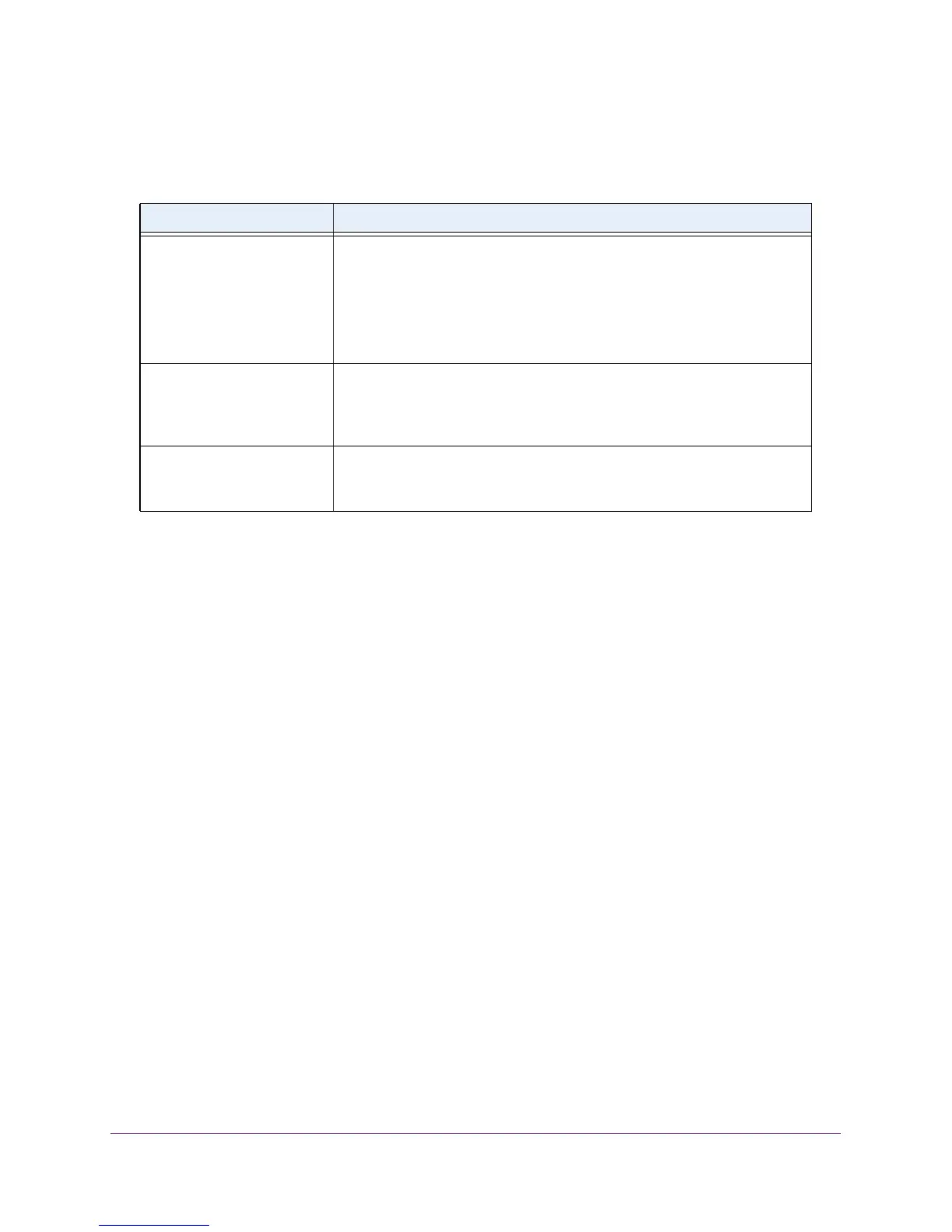
The following table describes the nonconfigurable information displayed on the Cable Test
screen.
Table 102. Cable test
Field Description
Cable Status This displays the cable status:.
• Normal. The
cable is working correctly.
• Open.
The cable is disconnected or there is a faulty connector.
• Short.
There is an electrical short in the cable.
• Cable T
est Failed. The cable status could not be determined. The
cable might in fact be working.
Cable Length The estimated length of the cable in meters. The length is displayed as a
range between the shortest estimated length and the longest estimated
length. Unknown is displayed if the cable length could not be determined.
The cable length is displayed only if the cable status is Normal.
Failure Location The estimated distance in meters from the end of the cable to the failure
location.
The failure location is only displayed if the cable status is Open or
Short.
Logs Overview
The switch generates messages in response to events, faults, or errors occurring on the
platform as well as changes in configuration or other occurrences. These messages are
stored locally and can be forwarded to one or more centralized points of collection for
monitoring purposes or long term archival storage. Local and remote configuration of the
logging capability includes filtering of messages logged or forwarded based on severity and
generating component.
View or Configure Buffered Logs
This log stores messages in memory based upon the settings for message component and
severity. On stackable systems, this log exists only on the top of stack platform. Other
platforms in the stack forward their messages to the top of stack log.
To view or configure buffered logs:
1. Prepare your computer with a static IP address in the 169.254.100.0 subnet, for
example, 169.254.100.201.
2. Connect an Ethernet cable from an Ethernet port on your computer to an Ethernet port on
the switch.
3. Launch a web browser
.
4. Enter the IP address of the switch in the web browser address field.
The default IP address of the switch is 169.254.100.100.
The Login screen displays.

 Loading...