DMTA-10026-01EN, Rev. D, January 2015
Chapter 1
38
Figure 1-18 Location of the PROBE and FOOT SWITCH connectors
To avoid the risk of electric shock, do not touch the conductors of the PROBE and
FOOT SWITCH connectors. The warning symbol between the connectors shown in
Figure 1-18 on page 38 warns of this electric shock risk.
1.6.2.2 RS-232 and VGA Out Connectors
The RS-232 and the VGA Out connectors are located at the back of the instrument, in
the upper section (see Figure 1-19 on page 39). A rubber cover protects each
connector.
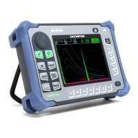
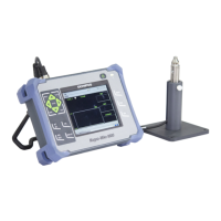
Along with the USB port (see “microSD and USB Port” on page 39), the Magna-
Mike 8600 allows the user to connect the instrument to a PC via a standard RS-232
port. PC communication requires the interface program (Olympus P/N: WinXL
[U8774010]) provided with the instrument for file transfers. The Magna-Mike 8600
can also communicate directly with other SPC programs.
Warning symbol
Connector for optional FOOT SWITCH
PROBE connector
 Loading...
