© 2011 Omnicell, Inc. 1-, 2-, 3-Cell Color Touch Installation and Service Guide/67-2014 Rev G
E-Box Service Guide 14-9
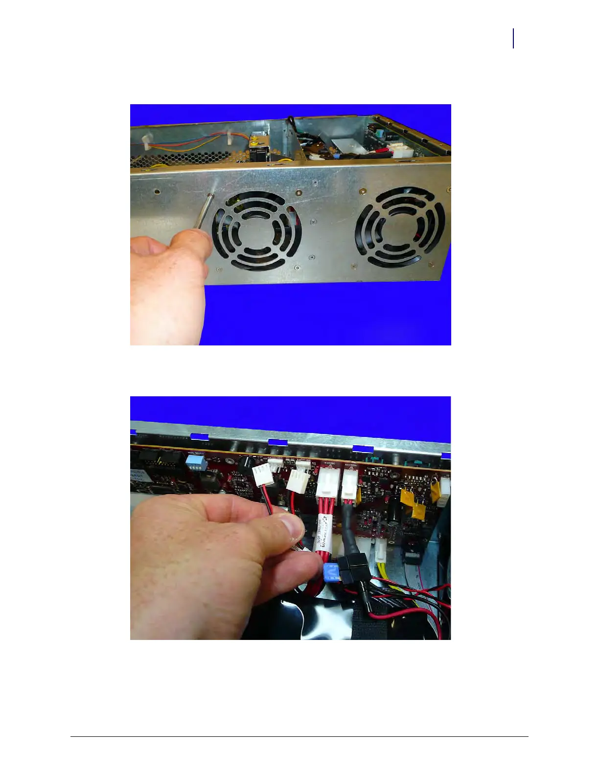
Remove/Replace the Fans
2. Replace the four screws that secure each cooling fan to the E-Box.
Figure 14-11. Replace the screws securing the fans to the E-Box
3. Connect the fan cables to the PowerCom4 board.
Figure 14-12. Connect the fan cables to the PowerCom4 board