© 2011 Omnicell, Inc. 1-, 2-, 3-Cell Color Touch Installation and Service Guide/67-2014 Rev G
CT PC Box Parts 1-5
Speaker
Replacement Procedure
1. Place the keyboard into position on the bezel.
2. Place the bracket into position on the bezel.
3. Secure the bracket with the six screws.
4. Replace the keyboard door bezel to the CT PC Box. See “Replacement Procedure” on page 1-3.
Speaker
Removal Procedure
1. Perform a graceful shutdown of the CT PC Box.
2. Remove the keyboard Door Bezel. See “Removal Procedure” on page 1-2.
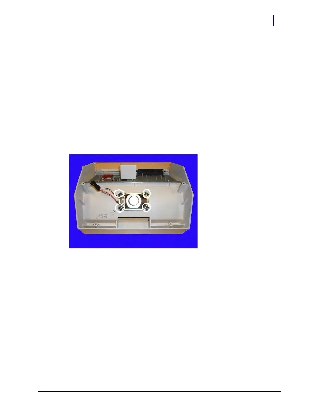
3. Remove the four flat nuts and remove the speaker.
Figure 1-7. Remove the four flat nuts
Replacement Procedure
1. Perform a graceful shutdown of the CT PC Box.
2. Remove the keyboard door bezel. See “Removal Procedure” on page 1-2.
3. If the speaker is still attached, remove the four flat nuts and remove the speaker.
4. Place the new speaker on the plastic pegs and secure the speaker with four new flat nuts.
5. Hot-glue the flat nuts into place.
6. Replace the keyboard door bezel. See “Replacement Procedure” on page 1-3.
7. Plug in the cabinet power cable.
8. Power up the cabinet and check the speaker to ensure that it is working.