© 2011 Omnicell, Inc. 1-, 2-, 3-Cell Color Touch Installation and Service Guide/67-2014 Rev G
CT PC Box Parts 1-9
LCD Data Cable
Replacement Procedure
1. Place the standoffs on the bottom of the LCD bezel into the keyholes on the frame, then slide
the LCD bezel to the right.
2. Replace the three 4-40 x 3/16 screws that secure the bezel to the top of the frame.
3. Replace the screw on the side of the frame.
4. Connect the following cables:
Inverter cable from J3 (back light for LCD)
The 24-pin keyboard harness assembly from bottom connector on the numeric pad bracket
LCD data cable
Touch screen data cable from the touch screen.
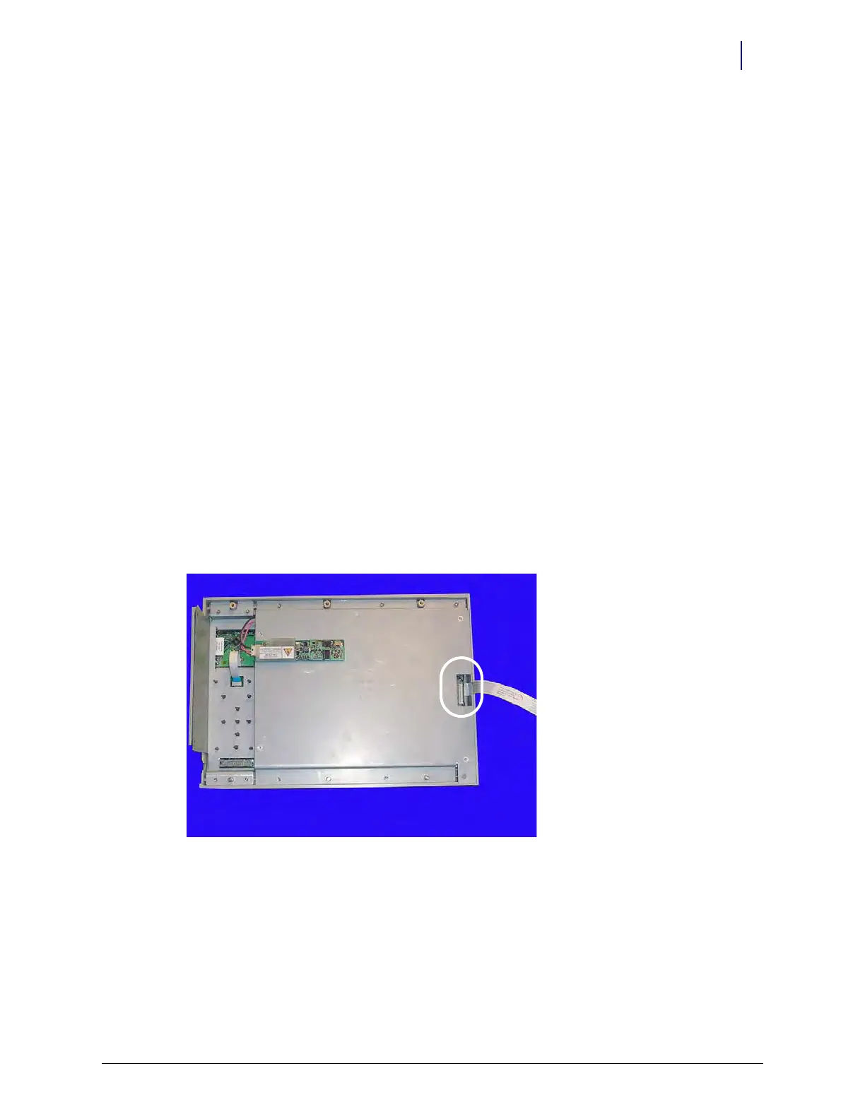
LCD Data Cable
Removal Procedure
1. Perform a graceful shutdown of the CT PC Box.
2. Unplug the power cord and all data cables from the rear of the box.
3. Remove the LCD bezel assembly. See “Removal Procedure” on page 1-6.
4. Remove the LCD data cable from the rear of the bezel assembly and from J1 on the
motherboard.
Figure 1-14. Remove the LCD data cable
Replacement Procedure
1. Attach the LCD data cable to the rear of the bezel assembly and to J1 on the motherboard.
2. Replace the LCD bezel assembly onto the frame.