© 2011 Omnicell, Inc. 1-, 2-, 3-Cell Color Touch Installation and Service Guide/67-2014 Rev G
CT PC Box Parts 1-15
Touch Pad
Touch Pad
Removal Procedure
1. Perform a graceful shut down of the CT PC Box.
2. Remove the LCD Bezel Assembly. See “Removal Procedure” on page 1-6.
3. Remove the LCD display and touch screen glass. See “Removal Procedure” on page 1-10.
4. Remove the Numeric Keypad. See “Removal Procedure” on page 1-12.
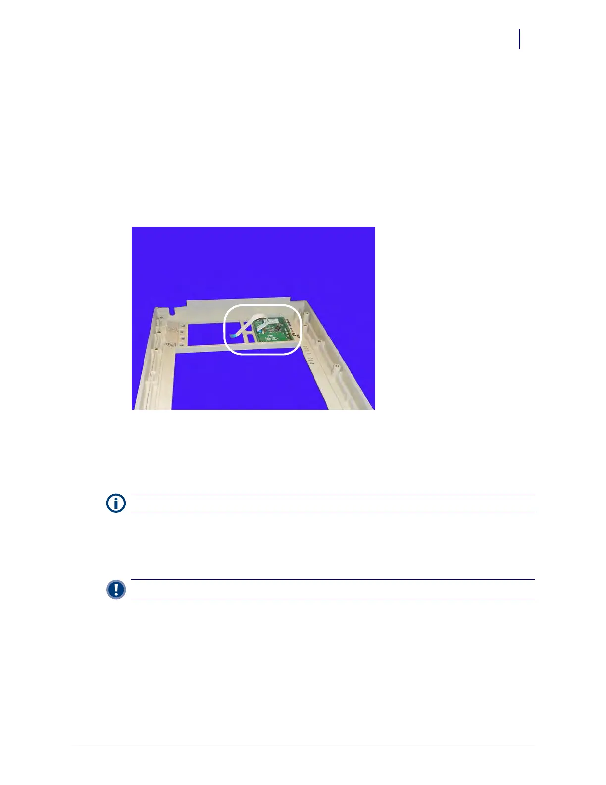
5. Remove the touch pad and flex cable from the bezel.
k
Figure 1-22. Remove the touch pad and flat flex cable.
6. Disconnect the flex cable from the touch pad, if necessary.
Replacement Procedure
1. Connect the flex cable to the touch pad and place the assembly into the bezel. Ensure that the
touch pad goes into the bezel with the flex cable closer to the keyboard.
2. Connect the other end of the flex cable to the keyboard.
.
3. Replace the Numeric Keypad. See “Replacement Procedure” on page 1-14.
4. Replace the touch screen glass and LCD display. See “Replacement Procedure” on page 1-12.
5. Replace the LCD bezel assembly. See “Replacement Procedure” on page 1-9.
Note: If a new flex cable is being installed, be sure to bend the blue tabs on both ends of the cable.
Important: Verify the cable is not twisted between connector points.