1-16 CT PC Box Parts
Color Touch PC Box
1-, 2-, 3-Cell Color Touch Installation and Service Guide/67-2014 Rev G © 2011 Omnicell, Inc.
Color Touch PC Box
PowerCom2 CT PC Box Removal
Prior to swapping out the PowerCom2 CT PC Box, establish a process for supply/medication
removal so the nurses can track transactions while the system is down. (Example forms are
located in the Implementation Guide.)
1. Perform a graceful shutdown of the cabinet software, then power down the cabinet and
disconnect the machine from the wall outlet.
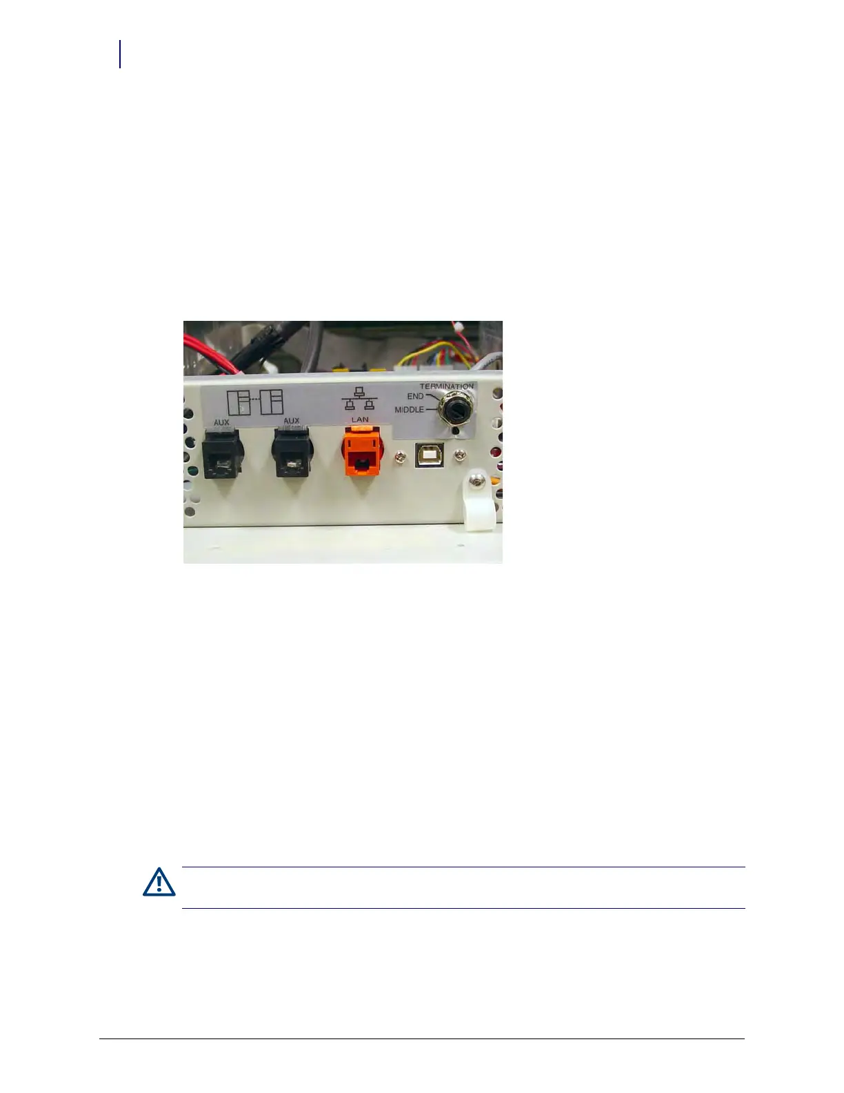
2. Disconnect the LAN cable and the AUX cables from the rear of the CT PC Box.
Figure 1-23. Location and labels for LAN and AUX cable connections on CT PC Box
3. Remove the CT PC Box.
a. Pull open the keyboard door to access the screws fastening the CT PC Box to the frame.
b. Remove the buttonhead 8-32 x 7/8” and 8-32 x 3/8” screws.
c. Slowly pull the CT PC Box from the frame until the side-mounted slides lock and stop.
d. Unlock the CT PC Box cover with the cam lock key #2036.
e. Remove the cover by lifting the front end and pulling away from the cabinet.
f. Disconnect the SPC cables from the PowerCom2 board. Remove the cables from
underneath the power supply and out of the sheet metal enclosure.
g. Tuck the SPC cables - still connected to the wireway - under the transport handle on the
side of the OmniSupplier frame.
h. Release the CT PC Box from the slides, carefully remove it from the cabinet and set it on a
flat surface.
Caution:
The CT PC Box is heavy. Trying to lift or remove the box alone could result in injury. Use a second
person to help lift and remove the CT PC Box from the OmniSupplier cabinet.