1-6 CT PC Box Parts
LCD Bezel Assembly
1-, 2-, 3-Cell Color Touch Installation and Service Guide/67-2014 Rev G © 2011 Omnicell, Inc.
LCD Bezel Assembly
Removal Procedure
1. Perform a graceful shutdown of the CT PC Box.
2. Unplug the cabinet power cable from the outlet.
3. Remove the screws that secures the CT PC Box to the cabinet.
Pharmacy cabinets PC box screws are accessed by opening the keyboard door and using the
T15 Torx driver. [6-32x1/4 BH screws]
Supply cabinet PC box screws are accessed under the box at the front corners, using a T-10
Tor x dr iver. [8-32x3/8 SHC screws]
4. Pull the CT PC Box forward about halfway out of the cabinet.
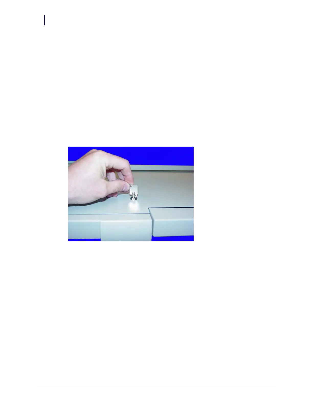
5. Use the #2036 key to unlock the top cover of the CT PC Box.
Figure 1-8. Use the 2036 key to unlock the CT PC Box cover
6. Remove the cover.
7. Disconnect the following cables from inside the CT PC Box:
Inverter cable from J3
The 24-pin keyboard harness assembly from the numeric keypad
LCD data cable
Touch s cre en data cable