1-8 CT PC Box Parts
LCD Bezel Assembly
1-, 2-, 3-Cell Color Touch Installation and Service Guide/67-2014 Rev G © 2011 Omnicell, Inc.
8. Remove the 6-32 x 3/16” flathead screw securing the bezel to the CT PC Box frame using a
T10 Torx driver.
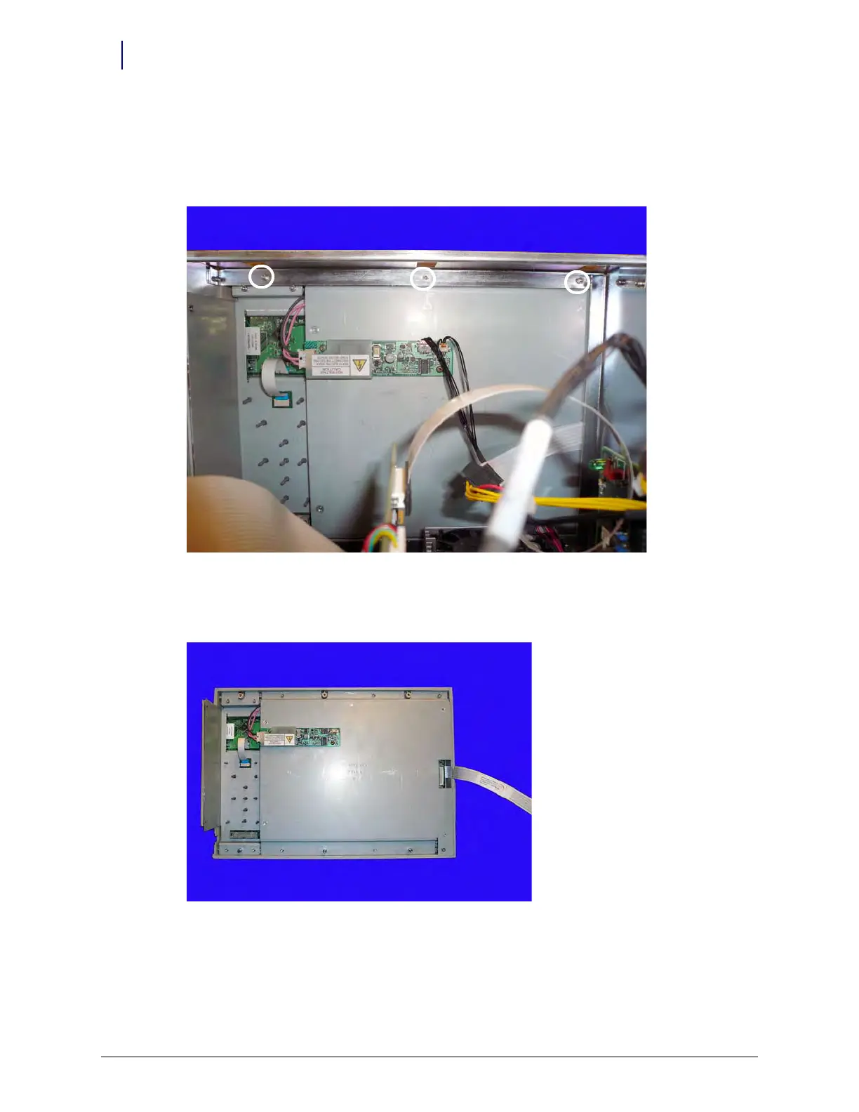
9. Remove the three 4-40 x 3/16 screws using a 9/64” Allen wrench, then remove the LCD bezel
assembly.
Figure 1-12. Remove the three screws securing the bezel to the CT PC Box frame
10. Slide the LCD bezel assembly to the left; remove the standoffs from the keyholes and pull the
LCD bezel away from the frame.
Figure 1-13. Remove the LCD bezel assembly from the CT PC Box