124
Control
14.01.04 Stepping motor drive
The stepping motor control unit has the following basic setting:
Motor 1: 6 A, SIN 4
Motor 2: 6 A, SIN 4
Current reduction 30%, coupling of motor 1 and motor 2
The settings are loaded. Software number: 79-001 358-91/002
Please refer to chapter 14.02.05 Stepping motor drive errors for the LED status
indicators.
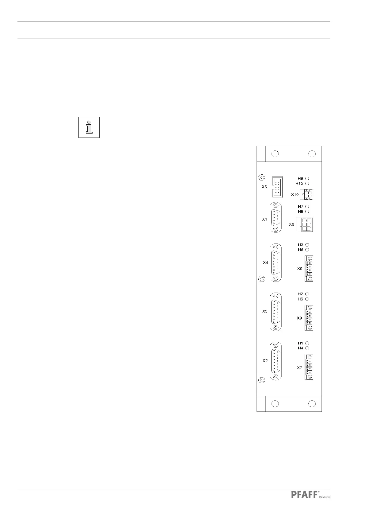
Plug connection
X5 (Bootstrap)
PIN Signal PIN Signal
1 .................... GND 2 ............... BOOTSTRAP
3 .................... RESIN\ 4 ............... n.c.
5 .................... TxD 6 ............... RxD
7 .................... 12 Vin 8 ............... Vpp processor
9 .................... 5 V 10 ............. n.c.
X10 (Carriage monitoring)
PIN Signal PIN Signal
1 .................... 12 V 3 ............... GND
2 .................... Switch 4 ............... n.c.
X1 (CAN bus)
PIN Signal PIN Signal
1 ........................ 6
2 ........................ 7
3 .................... DoRi + 8 ............... DoRi -
4 .................... GND 9 ............... GND
5
X6 (Supply)
PIN Signal PIN Signal
1 .................... +24 VSM 4 ............... GND 24 VSM
2 .................... +80 VSM 5 ............... GND 80 VSM
3 .................... +80 VSM 6 ............... GND 80 VSM