123
Control
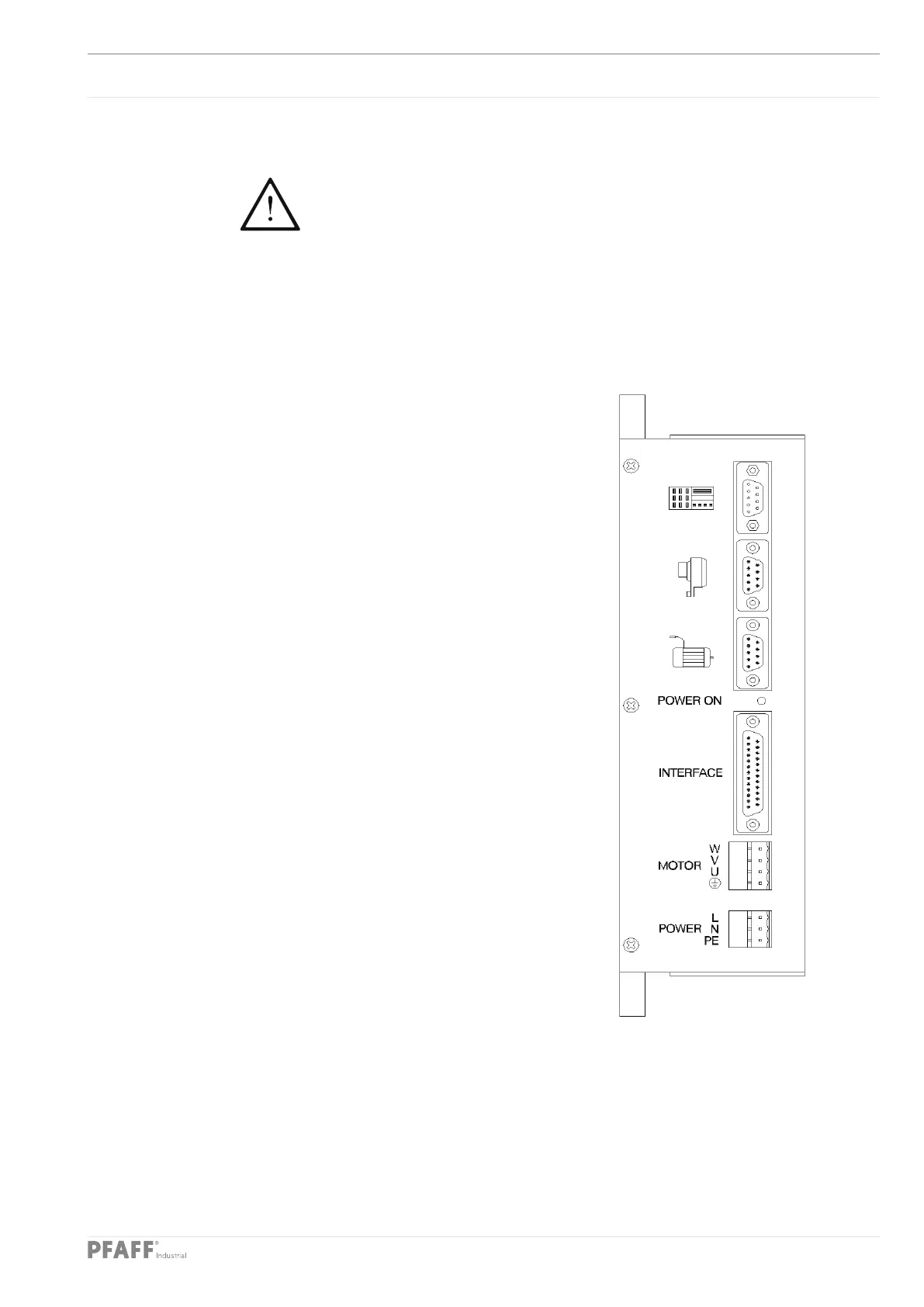
14.01.03 Sewing drive A22
The sewing drive control unit is supplied from the factory with the necessary
operating software already installed. This should only be replaced by the
appropriate technical staff.
The “Power on” LED indicates that it is ready for operation. Diagnostic functions and
fuses are not provided. Please refer to chapter 14.02.04 Sewing drive errors when error
messages appear on the machine display.
Plug connection
X2 (Position sensor)
PIN Signal PIN Signal
1 .................... KA 6
2 .................... KB 7
3 .................... KC 8
4 .................... ADTC2 9 ............... GND
5 .................... + 5V
X3 (Interface)
PIN Signal PIN Signal
1 .................... GND 14 ............. A
2 .................... TxD 15 ............. A\
3 .................... RxD 16 ............. B
4 .................... TxD\ 17 ............. B\
5 .................... RxD\ 18 ............. Index
6 ........................ 19 ............. Index\
7 .................... GND 20
8 ........................ 21
9 .................... REF1 22
10 .................. REF1\ 23
11 .................. REF2 24
12 .................. REF2\ 25
13 .................. GND 26
X6 (Mains)
PIN Signal PIN Signal
1 .................... PE 2 ............... N
3 .................... L1
X14 (Motor)
PIN Signal PIN Signal
1 .................... PE 3 ............... V
2 .................... U 4 ............... W
 Loading...


