134
Control
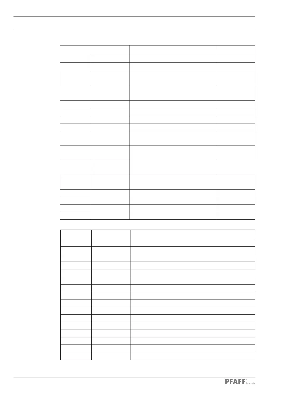
14.03.03 CAN node 3
Output Description Function Comment
OUT1 Y27U1 Positioning tube cylinder 1 down (vertical) Impulse valve
OUT2 Y27U2 Positioning tube cylinder 1 up (vertical) Impulse valve
OUT3 Y28U1 Positioning tube cylinder 2 down
(vertical)
Impulse valve
OUT4 Y28U2 Positioning tube cylinder 2 up
(vertical)
Impulse valve
OUT5 Y29U1 Infeed table lift 1 back Impulse valve
OUT6 Y29U2 Infeed table lift 1 forwards Impulse valve
OUT7 Y30U1 Infeed table lift 2 end positions Impulse valve
OUT8 Y30U2 Infeed table lift 2 special position Impulse valve
OUT9 Y31U1 Positioning tube cylinder 1 back
(horizontal)
Impulse valve
OUT10 Y31U2 Positioning tube cylinder 1 forwards
(horizontal)
Impulse valve
OUT11 Y32U1 Positioning tube cylinder 2 back
(horizontal)
Impulse valve
OUT12 Y32U2 Positioning tube cylinder 2 forwards
(horizontal)
Impulse valve
OUT13 Y33 Needles forwards Valve
OUT14 Y34 Turn-up at back Valve
OUT15 Y35 Infeed table extension on Valve
OUT16 Y36 Spreader forwards Valve
Input Description Function
IN1 E27U1 Positioning tube down
IN2 E27U2 Positioning tube up
IN3 E28 Positioning tube in the middle (vertical)
IN4 E29U1 Infeed table lift1 back
IN5 E29U2 Infeed table lift 1 forwards
IN6 E31U1 Positioning tube back
IN7 E31U2 Positioning tube forwards
IN8 E32 Positioning tube in the middle (horizontal)
IN9 E33 Needles back
IN10 E34U1 Turn-up at back
IN11 E34U2 Turn-up at front
IN12 E36 Spreader back
IN13
IN14 E38 Workholder bar table position
IN15
IN16
 Loading...


