© Koninklijke Philips Electronics N.V. 2006. All rights reserved.
User manual Rev. 01 — 12 January 2006 122
Philips Semiconductors
UM10161
Volume 1
Chapter 11: I
2
C interfaces
After a repeated START condition, I
2
C may switch to the master transmitter mode.
11.5.3 Slave Receiver mode
In the slave receiver mode, data bytes are received from a master transmitter. To initialize
the slave receiver mode, user write the Slave Address register (I2ADR) and write the I
2
C
Control Set register (I2CONSET) as shown in Table 119
.
I2EN must be set to 1 to enable the I
2
C function. AA bit must be set to 1 to acknowledge
its own slave address or the general call address. The STA, STO and SI bits are set to 0.
After I2ADR and I2CONSET are initialized, the I
2
C interface waits until it is addressed by
its own address or general address followed by the data direction bit. If the direction bit is
0 (W), it enters slave receiver mode. If the direction bit is 1 (R), it enters slave transmitter
mode. After the address and direction bit have been received, the SI bit is set and a valid
status code can be read from the Status register (I2STAT). Refer to Table 135
for the
status codes and actions.
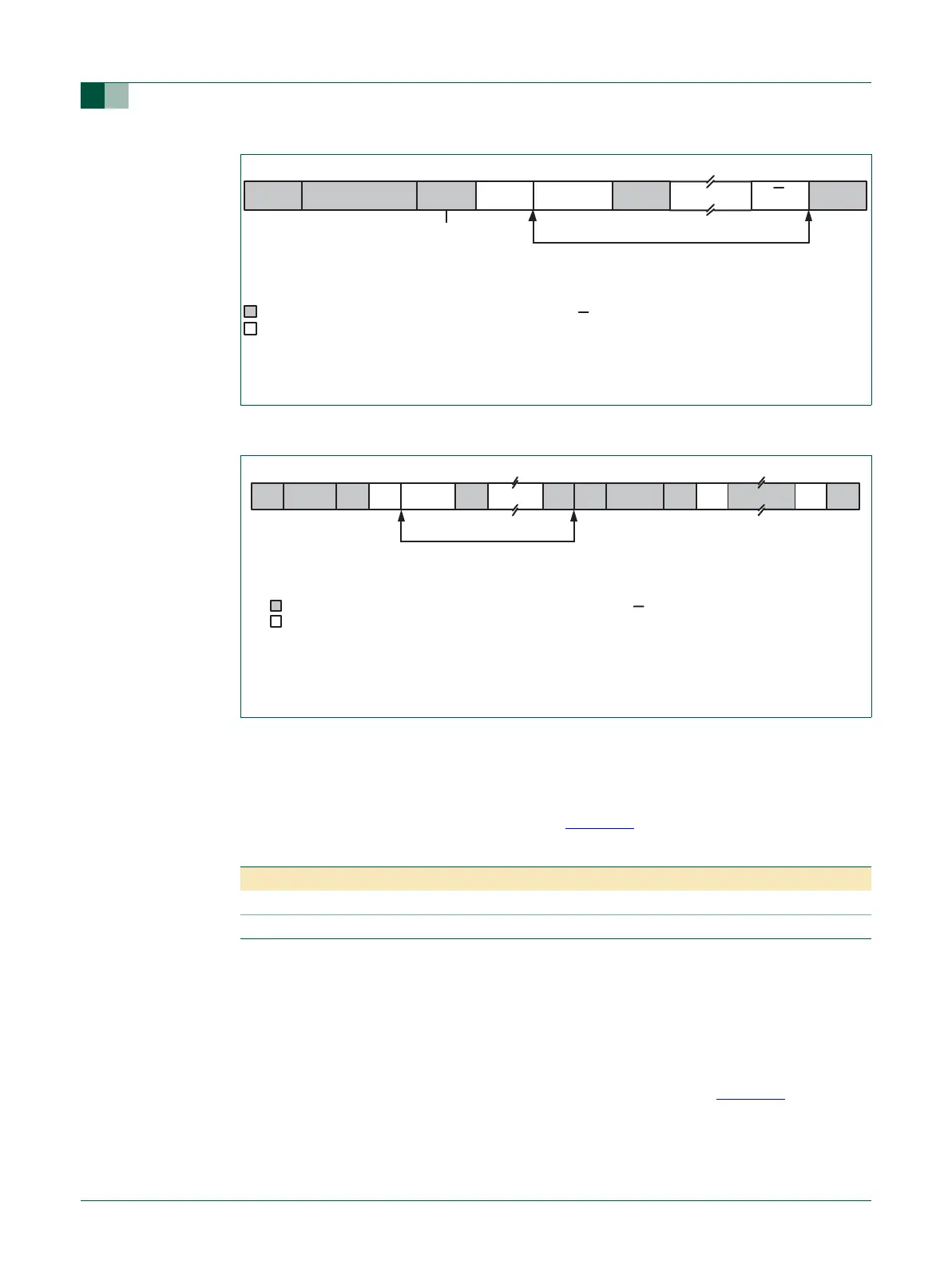
Fig 25. Format of Master Receiver mode
Fig 26. A Master Receiver switches to Master Transmitter after sending repeated START
DATA
A = Acknowledge (SDA low)
A = Not acknowledge (SDA high)
S = START Condition
P = STOP Condition
S SLAVE ADDRESS R A DATA P
Data Transferred
(n Bytes + Acknowledge)
“0” - Write
“1” - Read
From Master to Slave
From Slave to Master
A
A
A = Acknowledge (SDA low)
A = Not acknowledge (SDA high)
S = START Condition
P = STOP Condition
SLA = Slave Address
DATA
Data Transferred
(n Bytes + Acknowledge)
From Master to Slave
From Slave to Master
A DATA A ASLA R RS W PS SLA DATAAA
Table 119: I2C0CONSET and I2C1CONSET used to configure Slave mode
Bit 7 6 5 4 3 2 1 0
Symbol - I2EN STA STO SI AA - -
Value- 10001- -