© Koninklijke Philips Electronics N.V. 2006. All rights reserved.
User manual Rev. 01 — 12 January 2006 252
Philips Semiconductors
UM10161
Volume 1 Chapter 20: EmbeddedICE
20.8 DEBUG mode
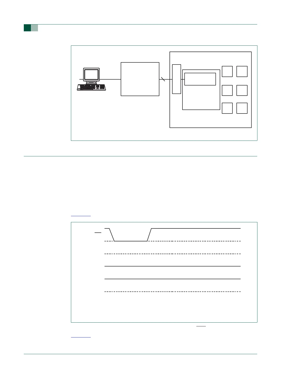
The Debug mode connects the JTAG pins to the embedded ICE for program debugging
using an emulator or other development tool
.
20.8.1 Enable Debug mode
The Debug mode is enabled through the use of the DBGSEL and RTCK pins.
To enable the debug mode, DBGSEL must be HIGH during and after the CPU is reset.
For normal (non-debug) operation, DBGSEL must be kept LOW at all times (see
Figure 65
)
For debugging with JTAG pins, RTCK must be HIGH as the RST
pin is released (see
Figure 66
). RTCK may be driven HIGH externally or allowed to float HIGH via its on-chip
pull-up. The RTCK output driver is disabled until the internal wake-up time has expired,
Fig 64. EmbeddedICE debug environment block diagram
ARM7TDMI-S
TARGET BOARD
EMBEDDED ICE
INTERFACE
PROTOCOL
CONVERTER
EMBEDDED ICE
JTAG PORT
5
serial
parallel
interface
host running debugger
(1) DBDSEL is tied or pulled LOW at all times. An internal pull-down will cause DBGSEL to be
LOW if it is not pulled HIGH externally.
(2) RTCK is not connected in the application and is pulled up internally.
Fig 65. Waveforms for normal operations (not in debug mode)
RST
DBGSEL
1
RTCK
2