© Koninklijke Philips Electronics N.V. 2006. All rights reserved.
User manual Rev. 01 — 12 January 2006 22
Philips Semiconductors
UM10161
Volume 1 Chapter 3: System control block
3.6 Other system controls
Some aspects of controlling LPC2101/02/03 operation that do not fit into peripheral or
other registers are grouped here.
Table 12: External Interrupt Polarity register (EXTPOLAR - address 0xE01F C14C) bit
description
Bit Symbol Value Description Reset
value
0 EXTPOLAR0 0 EINT0 is low-active or falling-edge sensitive (depending on
EXTMODE0).
0
1 EINT0 is high-active or rising-edge sensitive (depending on
EXTMODE0).
1 EXTPOLAR1 0 EINT1 is low-active or falling-edge sensitive (depending on
EXTMODE1).
0
1 EINT1 is high-active or rising-edge sensitive (depending on
EXTMODE1).
2 EXTPOLAR2 0 EINT2 is low-active or falling-edge sensitive (depending on
EXTMODE2).
0
1 EINT2 is high-active or rising-edge sensitive (depending on
EXTMODE2).
7:3 - - Reserved, user software should not write ones to reserved
bits. The value read from a reserved bit is not defined.
NA
(1) See Figure 10 “Reset block diagram including the wake-up timer” on page 35
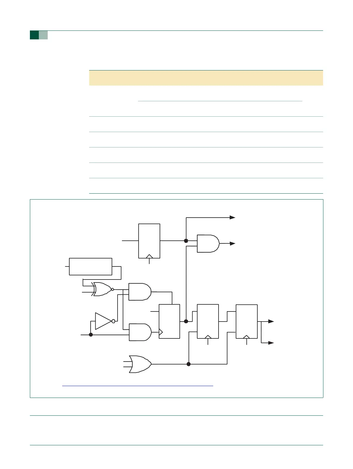
Fig 8. External interrupt logic
R
S
Q
D
Q
R
S
GLITCH
FILTER
wakeup enable
(one bit of EXTWAKE)
APB Read
of EXTWAKE
EINTi to wakeup
timer
1
PCLK
interrupt flag
(one bit of EXTINT)
APB read of
EXTINT
to VIC
1
EINTi
APB Bus Data
EXTMODEi
reset
write 1 to EXTINTi
EXTPOLARi
R
S
Q
PCLK
D Q
PCLK