© Koninklijke Philips Electronics N.V. 2006. All rights reserved.
User manual Rev. 01 — 12 January 2006 48
Philips Semiconductors
UM10161
Volume 1 Chapter 5: VIC
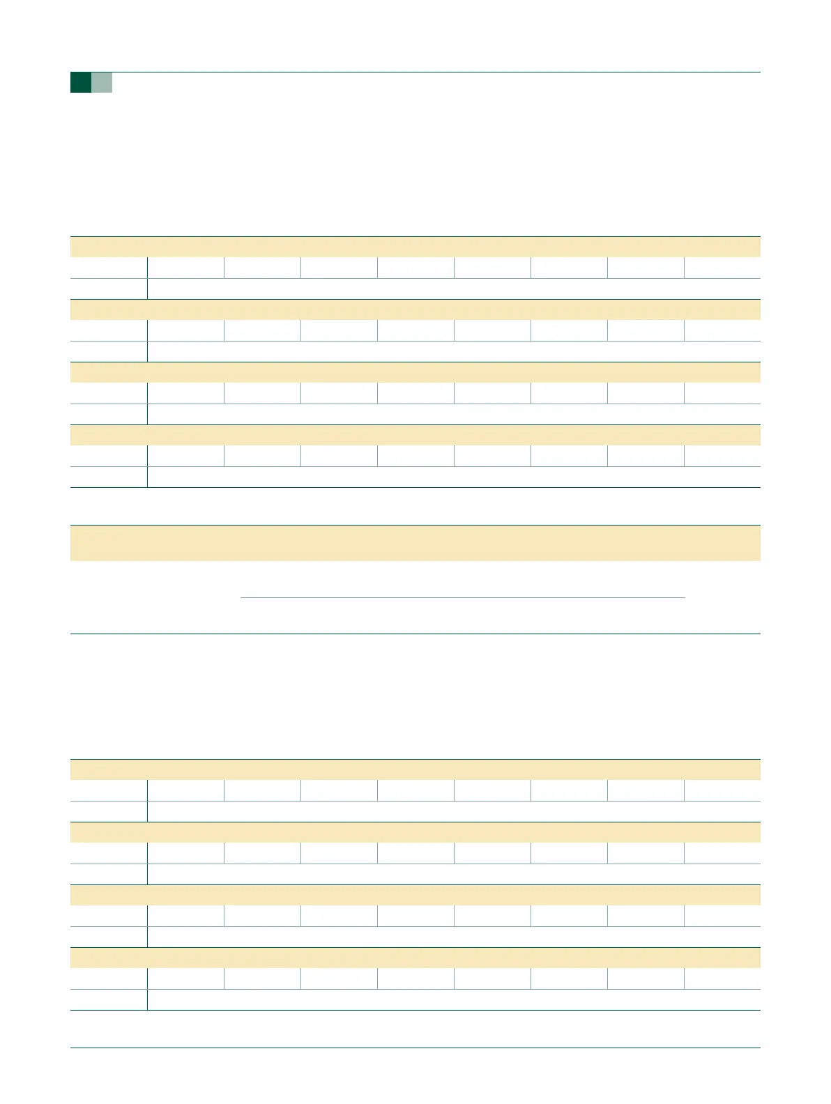
5.4.3 Raw Interrupt status register (VICRawIntr - 0xFFFF F008)
This is a read only register. This register reads out the state of the 32 interrupt requests
and software interrupts, regardless of enabling or classification.
5.4.4 Interrupt Enable register (VICIntEnable - 0xFFFF F010)
This is a read/write accessible register. This register controls which of the 32 interrupt
requests and software interrupts contribute to FIQ or IRQ.
Table 40: Raw Interrupt status register (VICRawIntr - address 0xFFFF F008) bit allocation
Reset value: 0x0000 0000
Bit 31 30 29 28 27 26 25 24
Symbol ----TIMER3TIMER2--
Access RO RO RO RO RO RO RO RO
Bit 23 22 21 20 19 18 17 16
Symbol ----I2C1AD0-EINT2
Access RO RO RO RO RO RO RO RO
Bit 15 14 13 12 11 10 9 8
Symbol EINT1 EINT0 RTC PLL SSP/SPI1 SPI0 I2C0 -
Access RO RO RO RO RO RO RO RO
Bit 7 6 5 4 3 2 1 0
Symbol UART1 UART0 TIMER1 TIMER0 ARMCore1 ARMCore0 - WDT
Access RO RO RO RO RO RO RO RO
Table 41: Raw Interrupt status register (VICRawIntr - address 0xFFFF F008) bit description
Bit Symbol Value Description Reset
value
31:0 See
VICRawIntr bit
allocation
table.
0 The interrupt request or software interrupt with this bit number is
negated.
0
1 The interrupt request or software interrupt with this bit number is
negated.
Table 42: Interrupt Enable register (VICIntEnable - address 0xFFFF F010) bit allocation
Reset value: 0x0000 0000
Bit 31 30 29 28 27 26 25 24
Symbol ----TIMER3TIMER2--
Access R/W R/W R/W R/W R/W R/W R/W R/W
Bit 23 22 21 20 19 18 17 16
Symbol ----I2C1AD0-EINT2
Access R/W R/W R/W R/W R/W R/W R/W R/W
Bit 15 14 13 12 11 10 9 8
Symbol EINT1 EINT0 RTC PLL SSP/SPI1 SPI0 I2C0 -
Access R/W R/W R/W R/W R/W R/W R/W R/W
Bit 7 6 5 4 3 2 1 0
Symbol UART1 UART0 TIMER1 TIMER0 ARMCore1 ARMCore0 - WDT
Access R/W R/W R/W R/W R/W R/W R/W R/W