© Koninklijke Philips Electronics N.V. 2006. All rights reserved.
User manual Rev. 01 — 12 January 2006 198
Philips Semiconductors
UM10161
Volume 1 Chapter 15: Timer0 and Timer1
15.7 Architecture
The block diagram for TIMER/COUNTER0 and TIMER/COUNTER1 is shown in
Figure 52
.
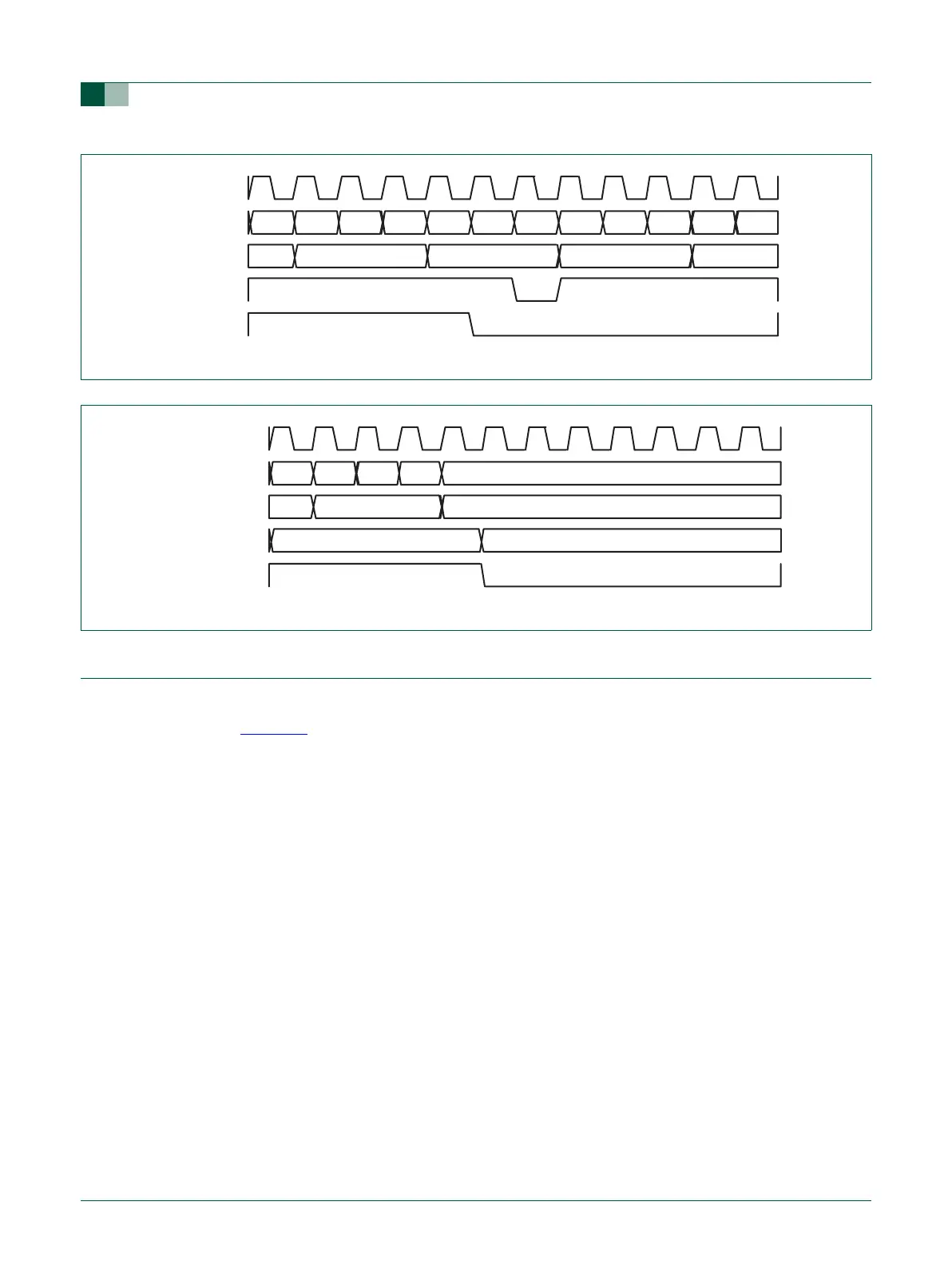
Fig 50. A timer cycle in which PR=2, MRx=6, and both interrupt and reset on match are enabled
PCLK
prescale
counter
interrupt
timer
counter
timer counter
reset
222200001111
45 6 0 1
Fig 51. A timer cycle in which PR=2, MRx=6, and both interrupt and stop on match are enabled
PCLK
prescale counter
interrupt
timer counter
TCR[0]
(counter enable)
220 01
45 6
1 0