© Koninklijke Philips Electronics N.V. 2006. All rights reserved.
User manual Rev. 01 — 12 January 2006 197
Philips Semiconductors
UM10161
Volume 1 Chapter 15: Timer0 and Timer1
15.5.13 Rules for single edge controlled PWM ouputs
1. All single edge controlled PWM outputs go LOW at the beginning of each PWM cycle
(timer is set to zero) unless their match value is equal to zero.
2. Each PWM output will go HIGH when its match value is reached. If no match occurs
(i.e. the match value is greater than the PWM cycle length), the PWM output remains
continuously LOW.
3. If a match value larger than the PWM cycle length is written to the match register, and
the PWM signal is HIGH already, then the PWM signal will be cleared on the next
timer reset.
4. If a match register contains the same value as the timer reset value (the PWM cycle
length), then the PWM output will be reset to LOW on the next clock tick. Therefore,
the PWM output will always consist of a one clock tick wide positive pulse with a
period determined by the PWM cycle length (i.e. the timer reload value).
5. If a match register is set to zero, then the PWM output will go to HIGH at the first time
the timer reaches its reset value and will stay HIGH continuously.
Note: When the match outputs are selected to perform as PWM outputs, the timer reset
(MRnR) and timer stop (MRnS) bits in the Match Control Register MCR must be set to
zero except for the match register setting the PWM cycle length. For this register, set the
MRnR bit to one to enable the timer reset when the timer value matches the value of the
corresponding match register.
15.6 Example timer operation
Figure 50 shows a timer configured to reset the count and generate an interrupt on match.
The prescaler is set to 2 and the match register set to 6. At the end of the timer cycle
where the match occurs, the timer count is reset. This gives a full length cycle to the
match value. The interrupt indicating that a match occurred is generated in the next clock
after the timer reached the match value.
Figure 51
shows a timer configured to stop and generate an interrupt on match. The
prescaler is again set to 2 and the match register set to 6. In the next clock after the timer
reaches the match value, the timer enable bit in TCR is cleared, and the interrupt
indicating that a match occurred is generated.
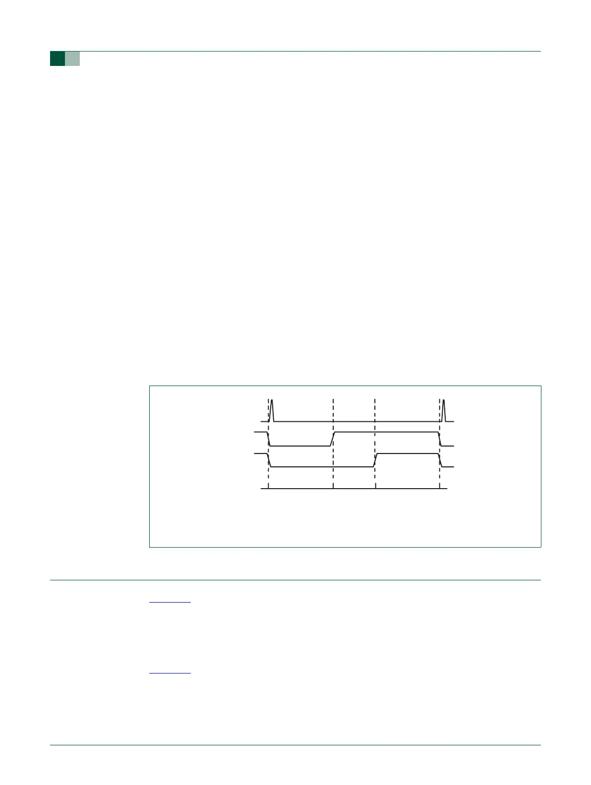
Fig 49. Sample PWM waveforms with a PWM cycle length of 100 (selected by MR3) and
MAT3:0 enabled as PWM outputs by the PWCON register.
100
(counter is reset)
04165
PWM0/MAT0
PWM1/MAT1
PWM2/MAT2 MR2 = 10
MR1 = 41
MR0 = 65