© Koninklijke Philips Electronics N.V. 2006. All rights reserved.
User manual Rev. 01 — 12 January 2006 70
Philips Semiconductors
UM10161
Volume 1 Chapter 7: Pin connect block
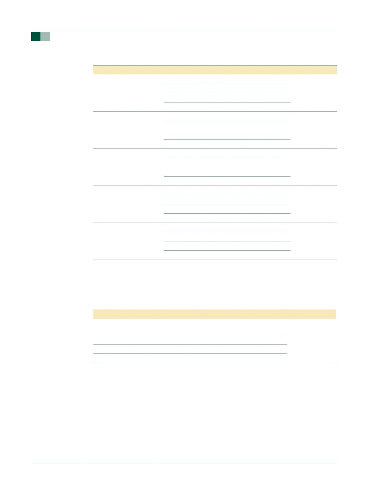
7.4.3 Pin function select register values
The PINSEL registers control the functions of device pins as shown below. Pairs of bits in
these registers correspond to specific device pins.
The direction control bit in the IO0DIR register is effective only when the GPIO function is
selected for a pin. For other functions, direction is controlled automatically. Each derivative
typically has a different pinout and therefore a different set of functions possible for each
pin. Details for a specific derivative may be found in the appropriate data sheet.
23:22 P0.27 0 0 GPIO Port 0.27 0
01TRST (JTAG)
10CAP2.0 (Timer2)
11Reserved
25:24 P0.28 0 0 GPIO Port 0.28 0
01TMS (JTAG)
10CAP2.1 (Timer2)
11Reserved
27:26 P0.29 0 0 GPIO Port 0.29 0
01TCK (JTAG)
10CAP2.2 (Timer2)
11Reserved
29:28 P0.30 0 0 GPIO Port 0.30 0
01TDI (JTAG)
1 0 MAT3.3 (Timer 3)
11Reserved
31:30 P0.31 0 0 GPIO Port 0.31 0
01TDO (JTAG)
10Reserved
11Reserved
Table 61: Pin function select register 1 (PINSEL1 - 0xE002 C004)
…continued
PINSEL1 Pin Name Value Function Value after reset
Table 62: Pin function select register bits
PINSEL0 and PINSEL1 Values Function Value after Reset
00 Primary (default) function, typically GPIO
port
00
01 First alternate function
10 Second alternate function
11 Third alternate function