© Koninklijke Philips Electronics N.V. 2006. All rights reserved.
User manual Rev. 01 — 12 January 2006 96
Philips Semiconductors
UM10161
Volume 1 Chapter 9: UART0
9.4 Architecture
The architecture of the UART0 is shown below in the block diagram.
The APB interface provides a communications link between the CPU or host and the
UART0.
The UART0 receiver block, U0RX, monitors the serial input line, RXD0, for valid input. The
UART0 RX Shift Register (U0RSR) accepts valid characters via RXD0. After a valid
character is assembled in the U0RSR, it is passed to the UART0 RX Buffer Register FIFO
to await access by the CPU or host via the generic host interface.
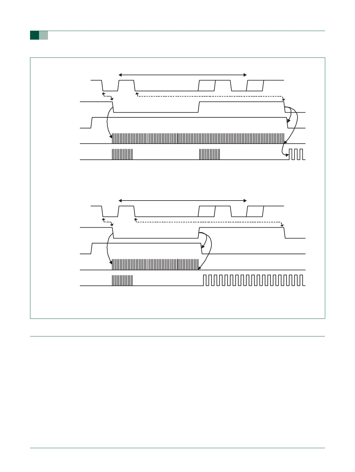
a. Mode 0 (start bit and LSB are used for auto-baud)
b. Mode 1 (only start bit is used for auto-baud)
Fig 17. Autobaud a) mode 0 and b) mode 1 waveform.
UART0 RX
start bit LSB of 'A' or 'a'
U0ACR start
rate counter
start bit0 bit1 bit2 bit3 bit4 bit5 bit6 bit7 parity stop
'A' (0x41) or 'a' (0x61)
16 cycles 16 cycles
16xbaud_rate
UART0 RX
start bit LSB of 'A' or 'a'
rate counter
'A' (0x41) or 'a' (0x61)
start bit0 bit1 bit2 bit3 bit4 bit5 bit6 bit7 parity stop
U0ACR start
16 cycles
16xbaud_rate