© Koninklijke Philips Electronics N.V. 2006. All rights reserved.
User manual Rev. 01 — 12 January 2006 54
Philips Semiconductors
UM10161
Volume 1 Chapter 5: VIC
I- Reserved 20-
25
0x0010 0000
0x0200 0000
TIMER2 Match 0 - 2 (MR0, MR1, MR2)
Capture 0 - 2 (CR0, CR1, CR2)
26 0x0400 0000
TIMER3 Match 0 - 3 (MR0, MR1, MR2, MR3) 27 0x0800 0000
Table 57: Connection of interrupt sources to the Vectored Interrupt Controller (VIC)
Block Flag(s) VIC Channel # and Hex
Mask
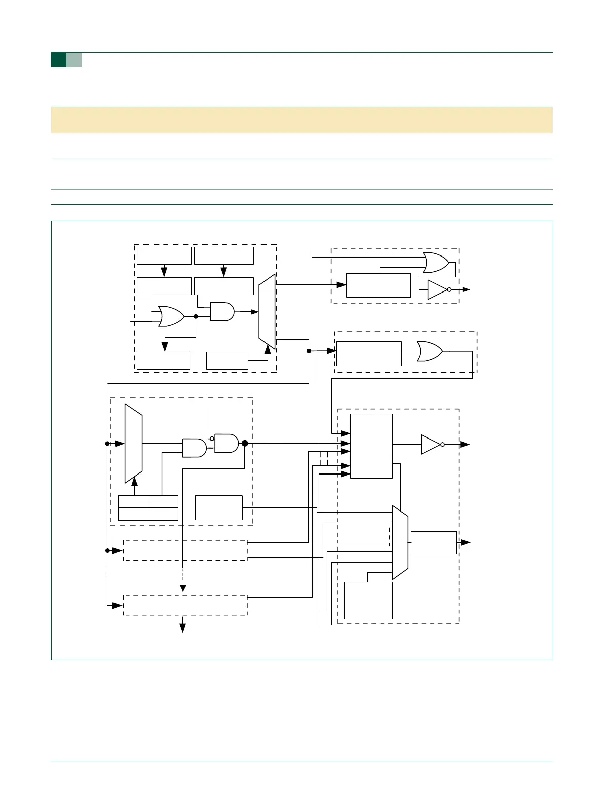
Fig 13. Block diagram of the Vectored Interrupt Controller (VIC)
FIQSTATUS
[31:0]
VECTIRQ0
HARDWARE
PRIORITY
LOGIC
IRQSTATUS
[31:0]
nVICFIQ
NonVectIRQ
non-vectored IRQ interrupt logic
priority 0
nVICIRQ
VECTADDR0[31:0]
VECTIRQ1
VECTIRQ15
VECTADDR1[31:0]
VECTADDR15[31:0]
IRQ
address select
for
highest priority
interrupt
VECTORADDR
[31:0]
VICVECT
ADDROUT
[31:0]
DEFAULT
VECTORADDR
[31:0]
priority14
priority15
priority2
priority1
VECTORADDR
[31:0]
SOURCE
VECTORCNTL[5:0]
ENABLE
vector interrupt 0
vector interrupt 1
vector interrupt 15
RAWINTERRUPT
[31:0]
INTSELECT
[31:0]
SOFTINT
[31:0]
INTENABLE
[31:0]
SOFTINTCLEAR
[31:0]
INTENABLECLEAR
[31:0]
VICINT
SOURCE
[31:0]
IRQSTATUS[31:0]
FIQSTATUS[31:0]
nVICFIQIN
non-vectored FIQ interrupt logic
interrupt priority logic
interrupt request, masking and selection
nVICIRQIN
VICVECTADDRIN[31:0]
IRQ