Chapter E - C-ARM AND IMAGING ARM
Planmeca ProMax E-67
PROMAX 3D: ADJUSTMENTS & CALIBRATIONS
Technical Manual
Darken the room sufficiently so that you will be able to see the image of the radiation beam on
the alignment tool (it is fluorescent and will glow when the radiation beam strikes it), but not so
dark that you cannot see the lines of the alignment rectangle.
Protect yourself from radiation and press the exposure button. The beam image appears on
the alignment tool. Observe the beam from behind the tube head.
CAUTION Radiation is generated when the exposure button is pressed. Take
adequate protection measures. Keep the exposure time as short as
possible.
X-ray units with 3D sensor V1:
The radiation beam must reach but not overlap the lines marked on the left and right of
the beam alignment tool (shown with arrows in Fig. 86).
X-ray units with 3D sensor V2:
Use the lines marked on the left and right of the beam alignment tool as reference lines
(shown with arrows in Fig. 86). The radiation beam must be 4 mm wider on both sides
(total 8 mm wider).
X-ray units with 3D s sensor:
Use the lines marked on the left and right of the beam alignment tool as reference lines
(shown with arrows in Fig. 86). The radiation beam must be 20 mm narrower on both sides
(total 40 mm narrower).
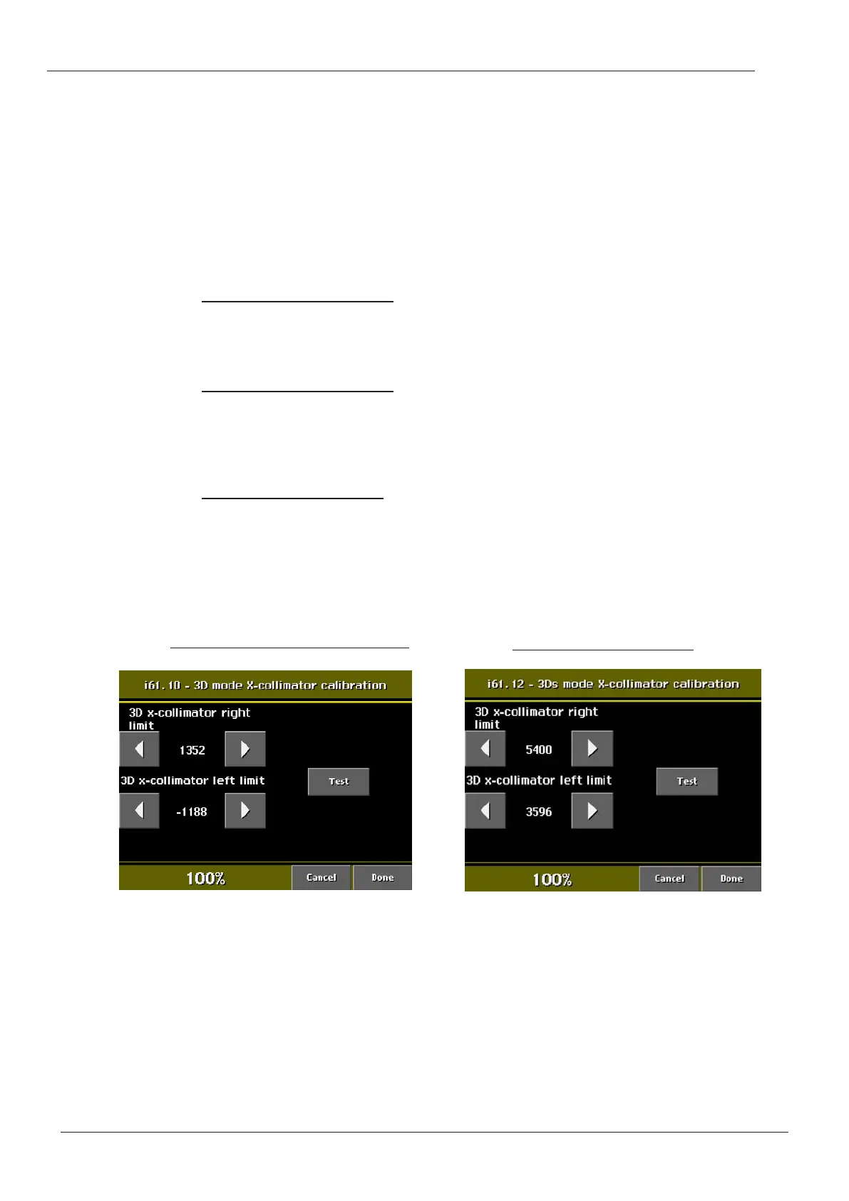
The X-ray beam horizontal position is adjusted on the X-collimator calibration (i61.10 or
i61.12) display.
Figure 87
Adjust the collimator position value with the x-collimator right and left limit arrow fields. The
left arrow field on the display adjusts the beam to the left, and the right arrow field to the right.
Drive the collimator to the selected position by touching the Test field.
Protect yourself from radiation and press the exposure button to check the position of the
beam. If necessary, repeat the procedure.
Accept the new position and exit the calibration mode by touching the Done field. The values
are not stored if you exit the mode with Cancel field.
X-ray units with 3D s sensor:
X-ray units with 3D sensor (V1 or V2):

 Loading...


