EasyManuals Logo

Planmeca ProMax Technical Manual

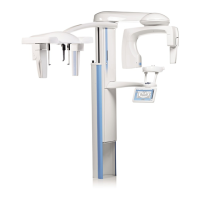
Planmeca ProMax
378 pages
To Next Page IconTo Next Page
To Previous Page IconTo Previous Page
Page #191 background imageLoading...
Page #191 background image
Chapter E - C-ARM AND IMAGING ARM
Planmeca ProMax E-93
PROMAX 3D: REPLACING THE SENSOR HEAD
Technical Manual
7 PROMAX 3D: REPLACING THE SENSOR HEAD
Detaching the sensor head from the C-arm
NOTE The indicator light is lit when the sensor is in use. Removing the sensor head when the
indicator light is lit might harm the sensor or cause image data loss.
Push in the C-arm electrical connector located on the sensor head quick connector mecha-
nism. This will disconnect the electrical connection between the sensor head and C-arm.
Figure 125
The locking knob can now be turned 180 degrees. This will release the sensor head locking
mechanism.
Figure 126
CBCT_s1.eps
Indicator light
C-arm electrical
connector
3D / 3D s sensor head
CBCT_s2.eps

Table of Contents

Other manuals for Planmeca ProMax

Questions and Answers:

Question and Answer IconNeed help?

Do you have a question about the Planmeca ProMax and is the answer not in the manual?

Planmeca ProMax Specifications

General IconGeneral
CategoryMedical Equipment
TypeCone Beam Computed Tomography (CBCT) System
SoftwarePlanmeca Romexis
Imaging ModesCBCT
Imaging Modalities2D Panoramic
X-ray GeneratorHigh Frequency Generator
Focal Spot Size0.5 mm
X-ray Tube Voltage60-90 kV
Exposure TimeVaries depending on imaging mode and parameters
DimensionsVaries significantly depending on model and configuration
WeightVaries significantly depending on model and configuration
Power Requirements50/60 Hz
Patient Positioningseated

Related product manuals