Chapter G - COLUMN
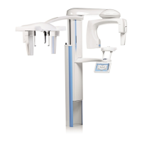
Planmeca ProMax G-25
REPLACING/UPGRADING SOFTWARE
Technical Manual
4 REPLACING/UPGRADING SOFTWARE
NOTE You can upgrade the software either by replacing the software chips (see section 4.1
“Replacing the CPU PCB software chips (alternative 1)” on page G-25) or by loading
the software from a computer (see section 4.2 “Loading the software from a computer
(alternative 2)” on page G-27).
4.1 Replacing the CPU PCB software chips (alternative 1)
WARNING
Always turn the X-ray unit off before removing the software chip
from its socket.
Never turn the unit on if the software chips are not in their sockets.
NOTE Take care of antistatic precautions when handling the software chip. Touch any
grounded metal part of the unit before touching the software chip.
NOTE The X-ray unit contains four software chips located in the CPU PCB, marked with
FLASH1, FLASH2, FLASH3 and FLASH4. The software versions used must be compati-
ble. Incompatible software versions should never be used together, the X-ray unit
would either be totally non-functional, produce continuous error messages, or some
important features or functions could be missing. However, no damage or safety haz-
ard would result if two non-compatible software chips are accidentally used together.
Check the markings above the sockets, never put the chip intended for one socket to
another socket.
NOTE The CPU PCB version B contains four software chips. Put the FLASH1 chip to the
socket marked FLASH 1, the FLASH2 chip to the socket FLASH 2, the FLASH3 chip to
the socket FLASH 3 and the FLASH4 chip to the socket FLASH 4.
Turn off the unit from the mains switch. Remove the column front cover as described in sec-
tion 2 “REMOVING THE COVERS” on page G-8.
Detach the Ethernet PCB from the CPU PCB as described in section 6.2 “ETHERNET PCB
and CPU PCB” on page G-35.
Remove the software chip from its socket with the special tool as illustrated in Fig. 48.
NOTE The orientation of the software chip is critical. Never try to force the chip into the
socket.
 Loading...
