Chapter E - C-ARM AND IMAGING ARM
Planmeca ProMax E-19
PANORAMIC BEAM AND PATIENT POSITIONING
MECHANISM ADJUSTMENT
Technical Manual
2.6 Patient positioning mechanism adjustment
Enter the panoramic exposure mode.
Remove the inner cover from tube head assembly, the sensor head covers and the lower
cover of the C-arm as well as the shoulder arm cover. Refer to section 5 “REMOVING THE
COVERS” on page E-77. Remove the cover of the patient support table, refer to section 2.1
“Patient support table cover” on page F-7.
Attach the ball phantom to the patient positioning mechanism adapter. Attach the sensor
head alignment tool to the sensor head connector.
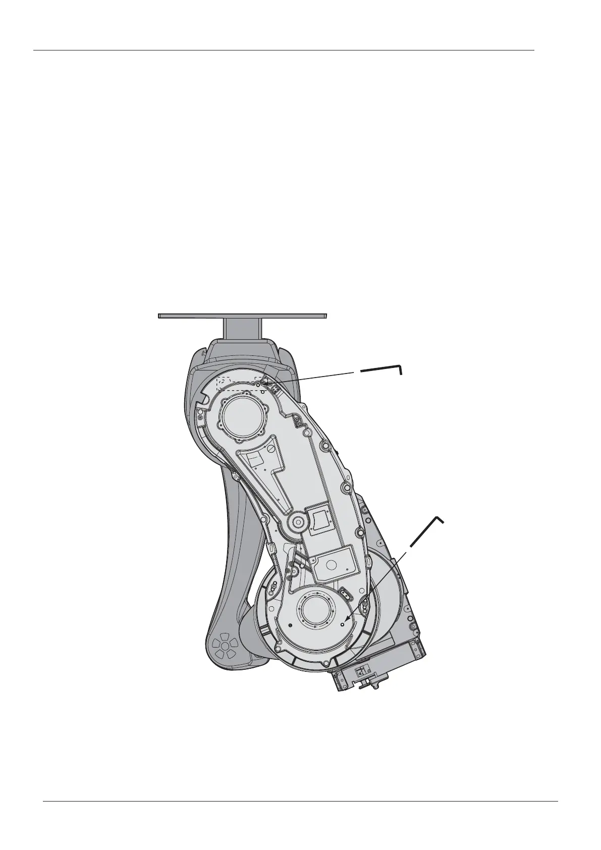
Slide the alignment pin through the hole in the shoulder joint so that it goes into the position-
ing holes in the shoulder arm and column as shown on the Fig. 26 below.
2.6.1 Adjustment in ball phantom’s x-direction
Manually position the C-arm as shown in Fig. 26 (C-arm perpendicular to the patient support
table). Note the position of the tube head and sensor head. Slide the alignment pin through
the hole in the elbow joint so that it goes into the positioning hole in the C-arm.
Figure 26
In case there is clearance either in the shoulder joint or in the elbow joint or both (i.e. one or
more arms can move even if the pins are in position), the adjustment may be unsuccessful if
the following action is not done: Push the arms to the same direction as far as they move. For
example: first push the shoulder arm to the right, then the elbow arm and finally the C-arm.
IMPORTANT: Do not push any of the arms to opposite direction from the others.
Dipin_2.eps
Shoulder joint pin
Elbow and C-arm
joint pin

 Loading...


