Page C-8 LTV
®
Series ventilator Operator’s Manual
p/n 10664, Rev. Y
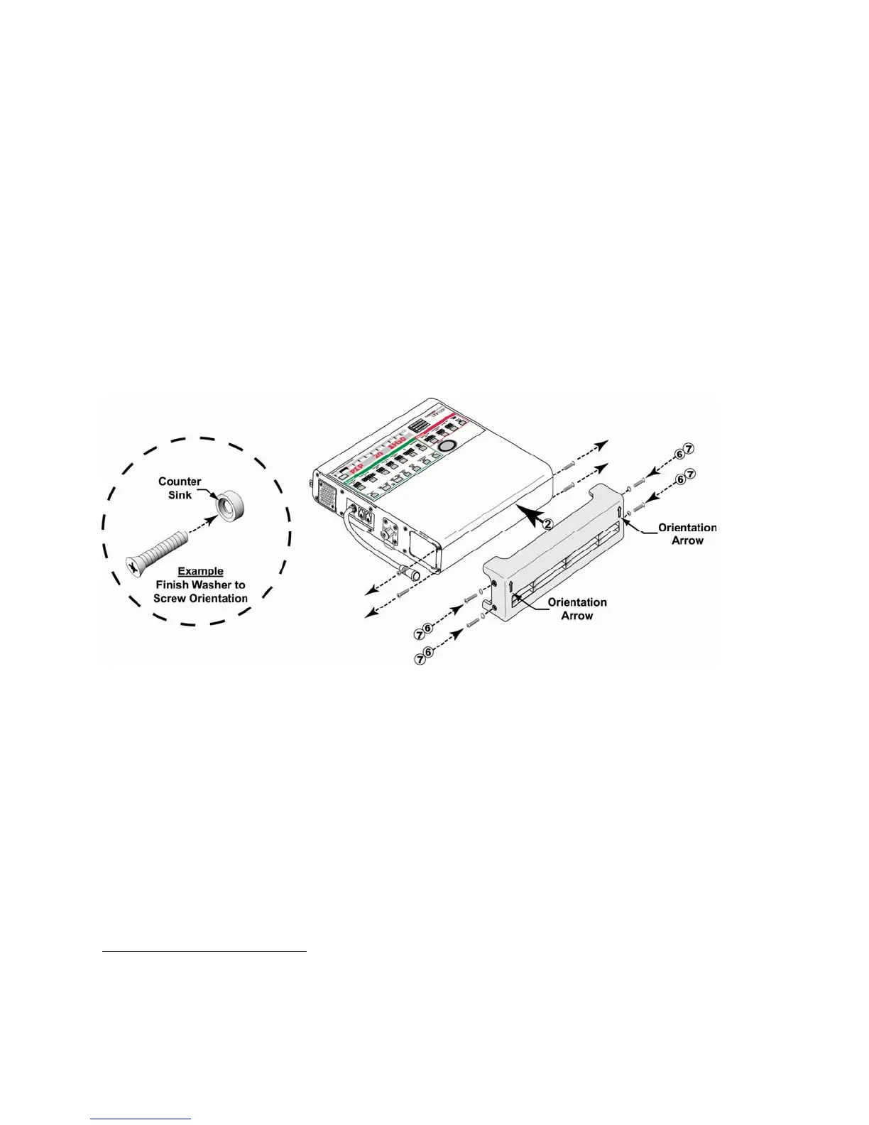
To Install the Lower Protective Boot
88
:
1) Lay the ventilator down (front up) and use a Phillips-head screwdriver to remove the four flat-
head mounting screws in the ventilator’s side panels, as indicated in the illustration.
• Do not remove the mating finish washers.
2) Orient the lower protective boot d to the ventilator as shown in the illustration. Move the boot
into position on the bottom of the ventilator and align its four screw holes with the corresponding
holes in the ventilator side panels.
• Ensure the orientation arrows on the bottom of the boot are aligned up, as shown.
4) Insert and thread four #4-40 X 1/2” flat-head mounting screws i with finish washers h through
the screw holes in the sides of the lower boot; as indicated in the illustration below.
5) Torque tighten all four screws in the boot to 20 in-oz (0.14 Nm) (do not over tighten to avoid
damage to the finish washers).
• Item g, #4-40 X 1/4” Flat-head mounting screw (1) P/N 10430
89
• Item h, Finish Washers (8) P/N 10191, 19119-001, or 19119-002
89
• Item i, #4-40 X 1/2” Flat-head mounting screws (6) P/N 10338
89
• Item j, #4-40 X 3/8” Flat-head mounting screws (2) P/N 10474
89
88
Refer to page C-9 for information concerning the appropriate accessories mounting screws or accessories
replacement screws location, type and length to use when removing or exchanging external accessories on
an LTV® Series ventilator.
89
Contained in Pulmonetic Systems Replacement Screws kit, P/N 11149.