3.4 Main Circuit Terminal Block Wiring
86 SIEPYEUOQ2A01G AC Drive Q2A Technical Manual
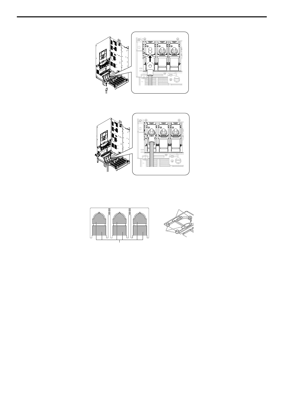
3. Wire the closed-loop crimp terminal to the main circuit terminal block.
Figure 3.29 Install the Electrical Wire
4. Tighten the nut to the specified torque.
Figure 3.30 Tighten the Terminal Block Nut
5. Check the signal from the wired terminal and use a diagonal-cutting pliers to remove areas of the wiring
cover cutaway section.
Cut the areas shown in Figure 3.31.
A - Cutaway section B - Use a diagonal-cutting pliers to clip this area.
Figure 3.31 Clip the Cutaway Section of the Wiring Cover
Note:
• Different drive models have different wiring cover shapes.
• Remove only the areas from the wiring cover that apply to the wired terminal. The drive will not keep its IP20 protective level
if areas that do not apply to the wired terminal are removed.
• Tightly hold the cutaway section when removing pieces of the cutaway section. Pieces of the cutaway section can fly out
and cause injury.
• Remove sharp edges from the wiring cover cutaway section to prevent damage to the wires.
• The drive might not keep its IP20 protective level if wires other than those specified by the manufacturer are used, even if
the wiring cover is used correctly. Contact the manufacturer or your nearest sales representative for more information.
• If the recommended gauge for the electrical wires are used, the wiring cover of the main circuit power input terminal and the
drive output terminal do not need to be attached. Attach the wiring cover when using the applicable gauge for electrical
wires.