Remote control basics
R&S
®
NRPxxS(N)
157User Manual 1177.5079.02 ─ 15
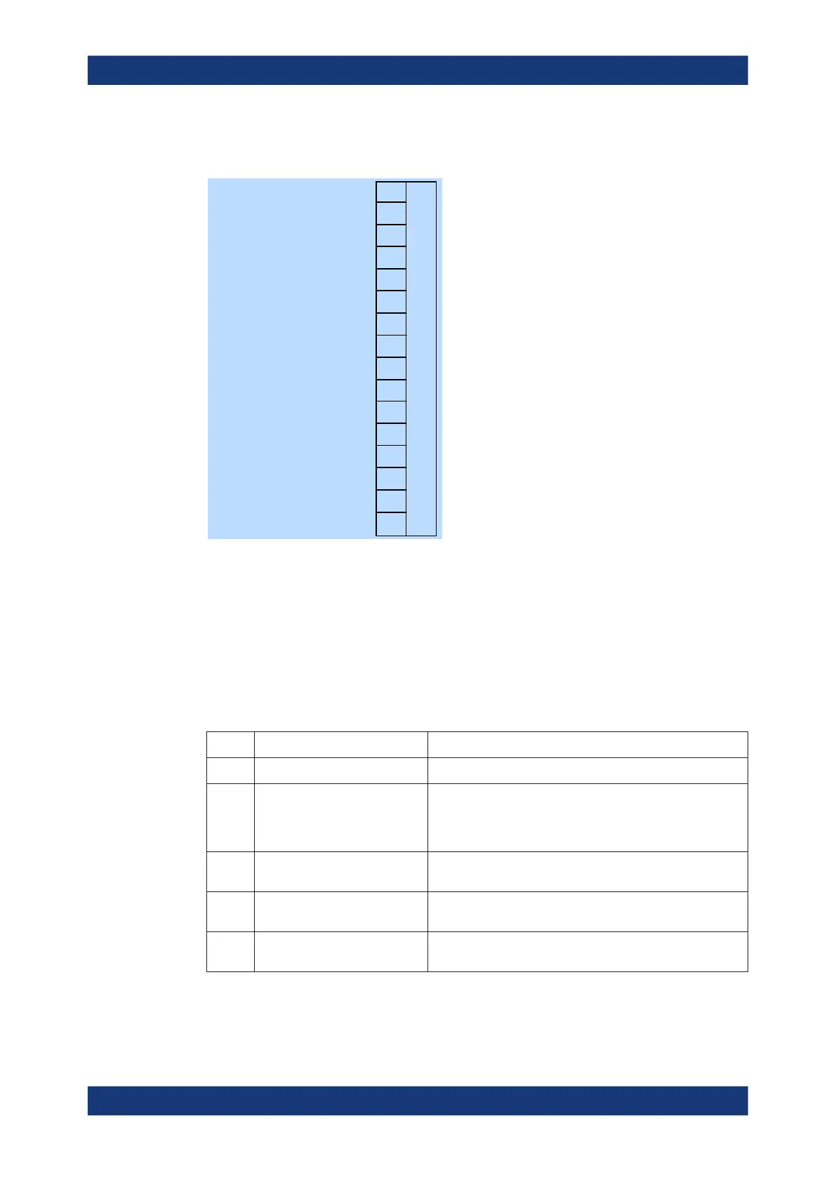
11.2.2 Device status register
0
1
2
3
4
5
6
7
8
9
10
11
12
13
14
15
Sensor error summary
Sensor error
Sensor error
Sensor error
Sensor error
0
0
Legacy locked
Reference PLL locked
0
0
0
0
0
0
0
Figure 11-2: Device status register
Querying the register:
●
STATus:DEVice:CONDition?
●
STATus:DEVice[:EVENt]?
Querying the static errors:
●
SYSTem:SERRor?
Table 11-4: Used device status bits and their meaning
Bit no. Short description Bit is set if
0 Sum of SERR bits Sum/combination of SERR bits 1 to 4.
1 SERR measurement not possi-
ble
Static error (SERR) exists. Certain parameter settings could
lead to a situation where subsequent measurements are not
possible; for example, a timeslot measurement with a config-
ured timeslot width of 0.0.
2 SERR erroneous results Static error exists. The measurement result is possibly incor-
rect.
3 SERR warning Static error exists. Status LED of the power sensor is slowly
flashing red.
4 SERR critical Critical static error exists. Status LED of the power sensor is
fast flashing red.
Status reporting system

 Loading...

