Power sensor tour
R&S
®
NRPxxS(N)
27User Manual 1177.5079.02 ─ 15
4 Power sensor tour
This chapter provides an overview of the available connectors and LEDs of the power
sensor.
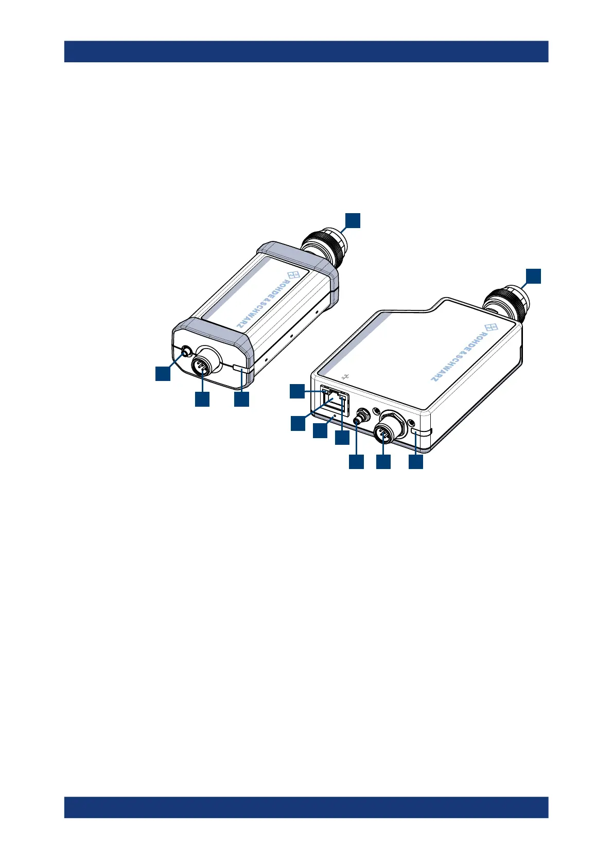
In Figure 4-1, the USB power sensor is shown on the left, the LAN power sensor is
shown on the right.
HOST
INTERFACE
IN:
3 V or 5 V logic
OUT: min. 2 V into 50
Ω
max. 5.3 V
TRIG2
I/0
PoE
SMART SENSOR TECHNOLOGY
NRP
SMART SENSOR TECHNOLOGY
NRP
1
1
4
2
2
3
34
8
5
6
7
Figure 4-1: R&S
NRP series power sensors (example)
1 = RF connector, see Chapter 4.1, "RF connector", on page 27
2 = Status LED, see Chapter 4.2, "Status information", on page 28
3 = Host interface connector, see Chapter 4.3, "Host interface", on page 29
4 = Trigger I/O connector, see Chapter 4.4, "Trigger I/O connector", on page 29
5 = Network status LED, see "Network status LED" on page 30
6 = LAN reset button, see "LAN reset button" on page 29
7 = LAN connector, see Chapter 4.5, "LAN PoE interface", on page 29
8 = Power over Ethernet status LED, see "Power over Ethernet status LED" on page 30
4.1 RF connector
The RF connector is used for connecting the power sensor to a device under test
(DUT) or a signal generator. See Chapter 3.4, "Connecting to a DUT", on page 15.
For maximum measurement accuracy, tighten the RF connector using a torque wrench
with a nominal torque as specified in the following table.
RF connector

 Loading...

