Remote control basics
R&S
®
NRPxxS(N)
161User Manual 1177.5079.02 ─ 15
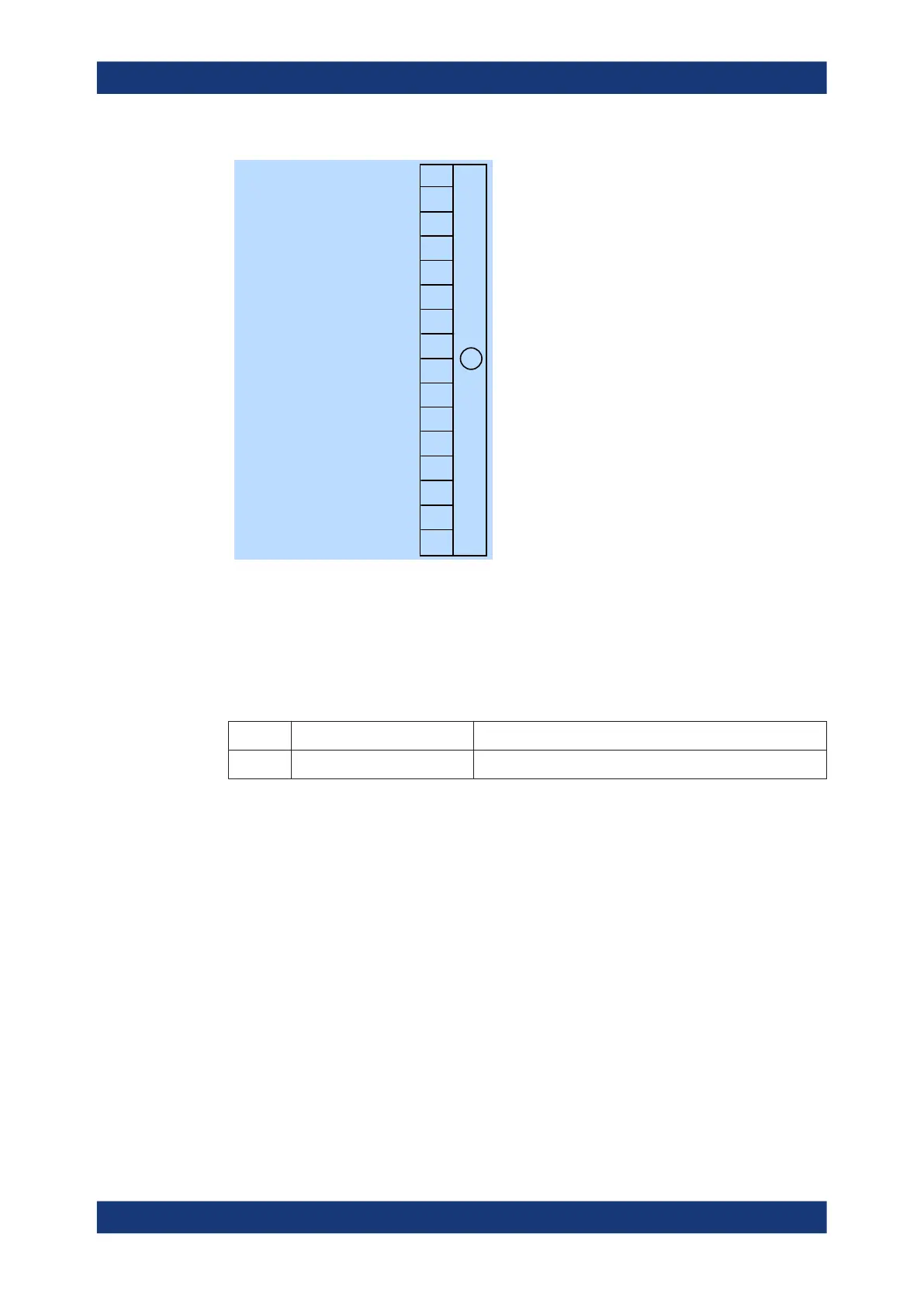
0
1
2
3
4
5
6
7
8
9
10
11
12
13
14
15
0
Sensor calibration
0
0
0
0
0
0
0
0
0
0
0
0
0
0
+
Figure 11-5: Questionable calibration status register
Querying the register:
●
STATus:QUEStionable:CALibration:CONDition?
●
STATus:QUEStionable:CALibration[:SUMMary][:EVENt]?
Table 11-7: Used questionable calibration status bits and their meaning
Bit no. Short description Bit is set if
1 Sensor calibration Zeroing of the power sensor was not successful.
11.2.4 Standard event status and enable register (ESR, ESE)
The ESR is already defined in the IEEE 488.2 standard. It is comparable to the EVENt
register of a SCPI register. The standard event status register can be read out by
*ESR?.
The ESE forms the associated ENABle register. It can be set and read by *ESE.
Status reporting system

 Loading...

