Browser-based user interface
R&S
®
NRPxxS(N)
44User Manual 1177.5079.02 ─ 15
Watts, dBm or dBµV. To change the unit, you must specify the desired value together
with the full new unit once.
Example:
To change the representation of a "Trigger Level" of 100µW into dBm, enter -10dbm in
the "Trigger Level" field. All future entries of solely numbers represent the value in
dBm. If you enter -15 in the field, the "Trigger Level" value is set to -15.00 dBm.
If you want to revert the value to Watts, enter 50uW. The "Trigger Level" value is set a
value of 50.00 µW, thus changing the unit for the further numeric entries.
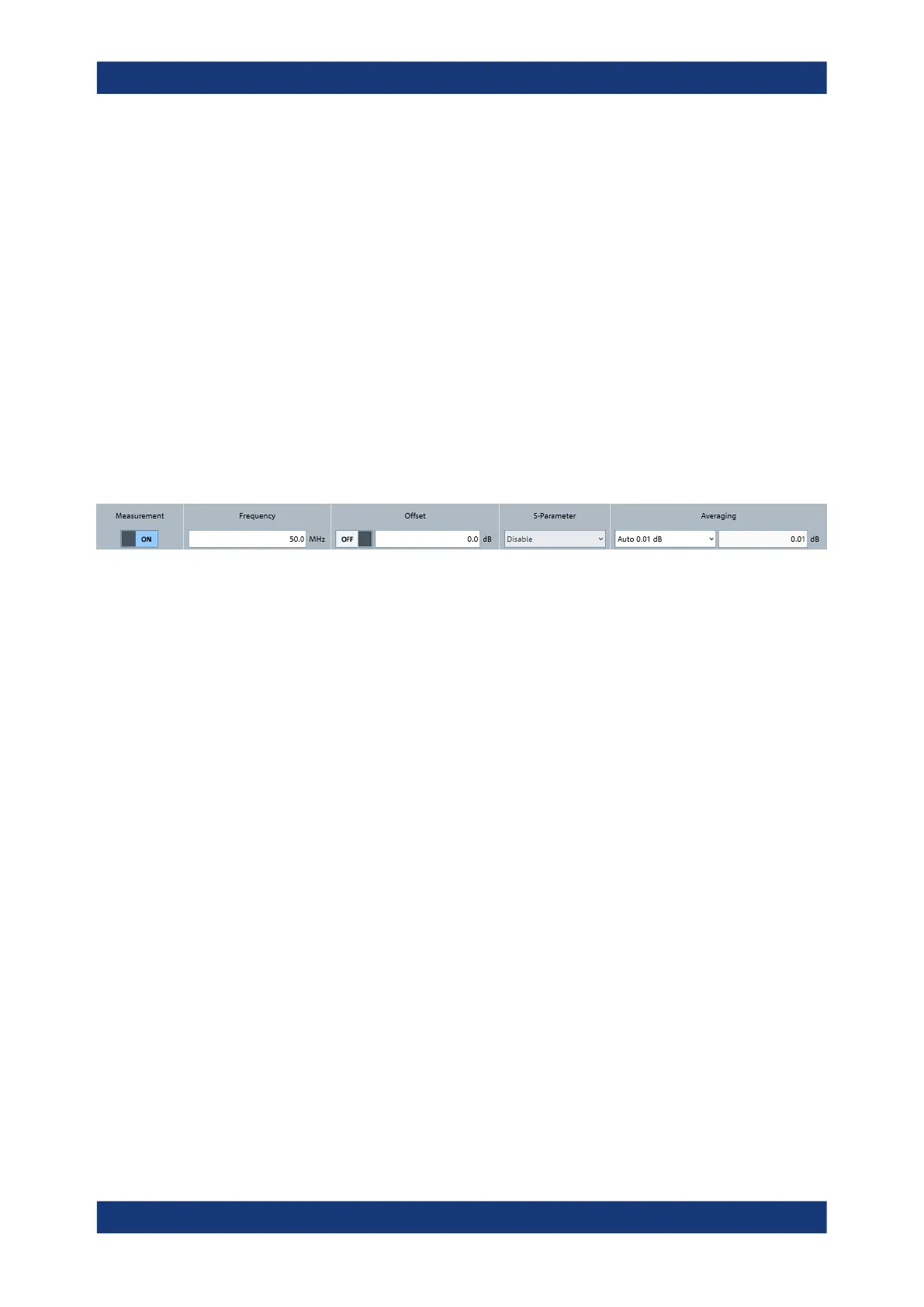
6.3 Common settings
Describes the common sensor settings that are available for all measurement modes.
Access: main dialog of the web user interface > top pane
Measurement................................................................................................................ 44
Frequency..................................................................................................................... 44
Offset.............................................................................................................................44
└ <State>........................................................................................................... 44
└ <Value>...........................................................................................................45
S-Parameter..................................................................................................................45
Averaging......................................................................................................................45
└ <Mode>...........................................................................................................45
└ <Value>...........................................................................................................45
Measurement
Enables or disables the measurement.
Remote command:
INITiate:CONTinuous
Frequency
Sets the carrier frequency of the applied signal. This value is used for frequency-
response correction of the measurement result.
Remote command:
[SENSe<Sensor>:]FREQuency
Offset
Groups the offset settings.
<State> ← Offset
Enables or disables the usage of the level offset.
Remote command:
[SENSe<Sensor>:]CORRection:OFFSet:STATe
Common settings

 Loading...

