Power sensor tour
R&S
®
NRPxxS(N)
28User Manual 1177.5079.02 ─ 15
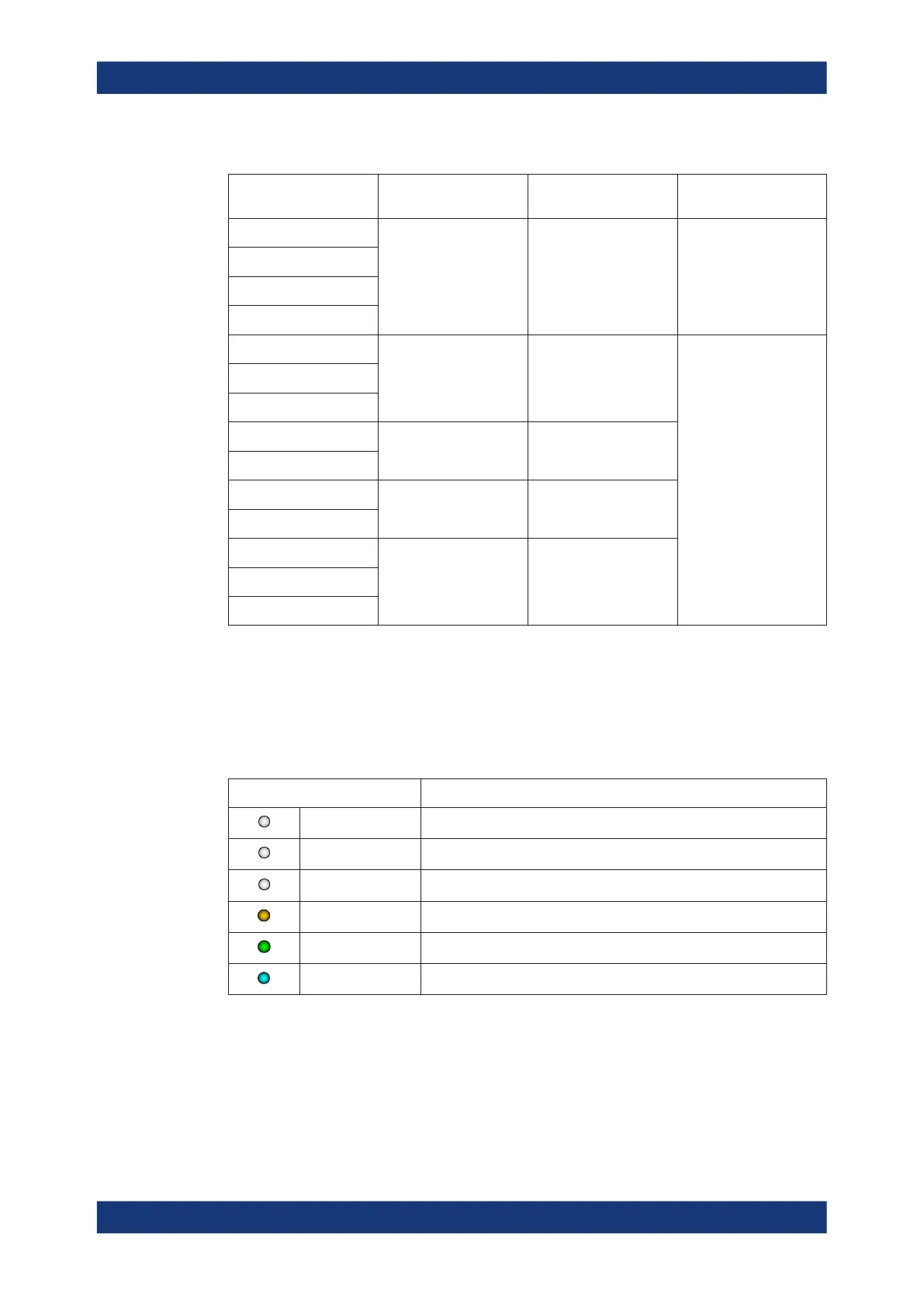
Table 4-1: R&S
NRPxxS(N) RF connector characteristics
Power sensor Male connector Matching female con-
nector
Tightening torque
R&S NRP8S
N N
1.36 Nm (12'' lbs)
R&S NRP8SN
R&S NRP18S
R&S NRP18SN
R&S NRP33S
3.50 mm 3.50 mm/ 2.92 mm/ SMA
0.90 Nm (8'' lbs)
R&S NRP33SN
R&S NRP33SN-V
R&S NRP40S
2.92 mm 3.50 mm/ 2.92 mm/ SMA
R&S NRP40SN
R&S NRP50S
2.4 mm 2.4 mm/ 1.85 mm
R&S NRP50SN
R&S NRP67S
1.85 mm 1.85 mmR&S NRP67SN
R&S NRP67SN-V
4.2 Status information
The status LED gives information about the state of the power sensor. The following
states are defined:
Indication State
White Idle state. The sensor performs no measurement and is ready for use.
Flashing white Firmware update is in progress
Slow flashing white Sanitizing in progress
Yellow Wait for trigger state
Green Measuring state
Turquoise blue Zeroing is in progress
Status information

 Loading...

