Operating concepts
R&S
®
NRPxxS(N)
38User Manual 1177.5079.02 ─ 15
5.5 R&S Power Viewer
The R&S Power Viewer is software that simplifies many measurement tasks. It is provi-
ded on your documentation CD-ROM and on the Rohde & Schwarz website as a sepa-
rate standalone installation package.
Required equipment
●
R&S NRPxxS(N) power sensor
●
R&S NRP‑ZKU cable or an R&S NRP‑Z5 sensor hub and an R&S NRP‑ZK6 cable
to connect the sensor to the computer
●
Computer with installed:
– R&S NRP Toolkit V 4.20 or higher
– R&S Power Viewer version 9.2 or higher (refer to the operating manual of the
R&S Power Viewer for a description of the installation process)
If you want to use an android device like a tablet or a smartphone, use the R&S Power
Viewer Mobile. For details, see Chapter 5.6, "R&S Power Viewer Mobile", on page 39.
Setup
NRP
3-Path Diode Power Sensor
MHz to GHz, 100 pW to 200 mW (−70 dBm to +23 dBm)
SMART SENSOR TECHNOLOGY
1
2
3
4
5
6
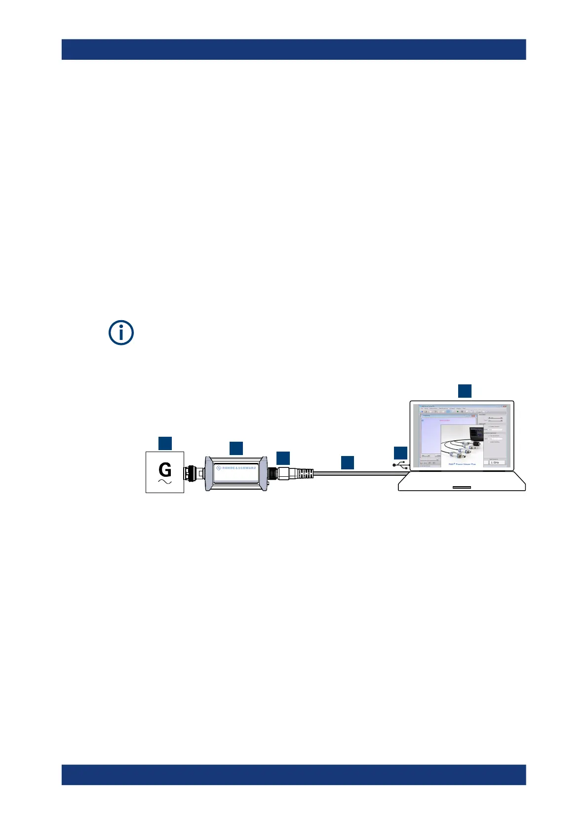
Figure 5-3: Setup with the R&S
Power Viewer
1 = Signal source
2 = R&S NRPxxS(N) power sensor
3 = Host interface connector
4 = R&S NRP‑ZKU cable
5 = USB connector
6 = Computer with installed R&S Power Viewer
1.
NOTICE! Incorrectly connecting or disconnecting the power sensor can damage
the power sensor or lead to erroneous results. Ensure that you connect or discon-
nect the power sensor as described in Chapter 3.4, "Connecting to a DUT",
on page 15.
Connect the power sensor to the signal source.
2. Connect the cables as shown in Figure 5-3.
For a detailed description, refer to Chapter 3.7.1.1, "Simple USB connection",
on page 18.
R&S
Power Viewer

 Loading...

