Operating concepts
R&S
®
NRPxxS(N)
37User Manual 1177.5079.02 ─ 15
●
Windows computer with installed:
– R&S NRP Toolkit V 4.20 or higher
– R&S NRPV version 3.2 or higher (refer to the operating manual of the
R&S NRPV for a description of the installation process)
Setup
1
2
3
4
5
6
NRP
3-Path Diode Power Sensor
MHz to GHz, 100 pW to 200 mW (−70 dBm to +23 dBm)
SMART SENSOR TECHNOLOGY
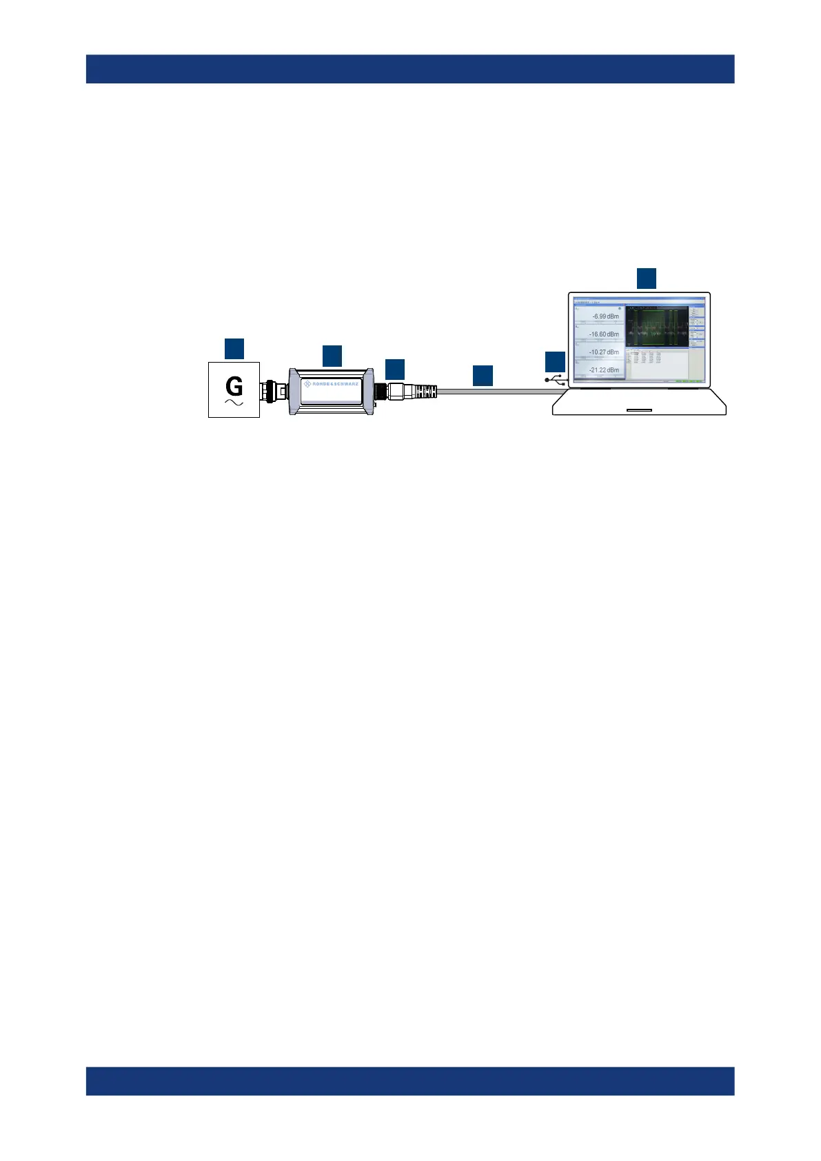
Figure 5-2: Setup with an R&S
NRPV
1 = Signal source
2 = R&S NRPxxS(N) power sensor
3 = Host interface connector
4 = R&S NRP‑ZKU cable
5 = USB connector
6 = Computer with installed R&S NRPV
1.
NOTICE! Incorrectly connecting or disconnecting the power sensor can damage
the power sensor or lead to erroneous results. Ensure that you connect or discon-
nect the power sensor as described in Chapter 3.4, "Connecting to a DUT",
on page 15.
Connect the power sensor to the signal source.
2. Connect the power sensor to the computer as shown in Figure 5-2.
For a detailed description, refer to Chapter 3.7.1.1, "Simple USB connection",
on page 18.
Starting a measurement
For a detailed description of how to measure in this setup, refer to the operating man-
ual of the R&S NRPV.
1. Start the R&S NRPV.
2. Execute zeroing.
Note: Turn off all measurement signals before zeroing. An active measurement
signal during zeroing causes an error.
3. Switch on the test signal of the signal source.
4. Start a measurement.
R&S
NRPV

 Loading...

