Power sensor tour
R&S
®
NRPxxS(N)
29User Manual 1177.5079.02 ─ 15
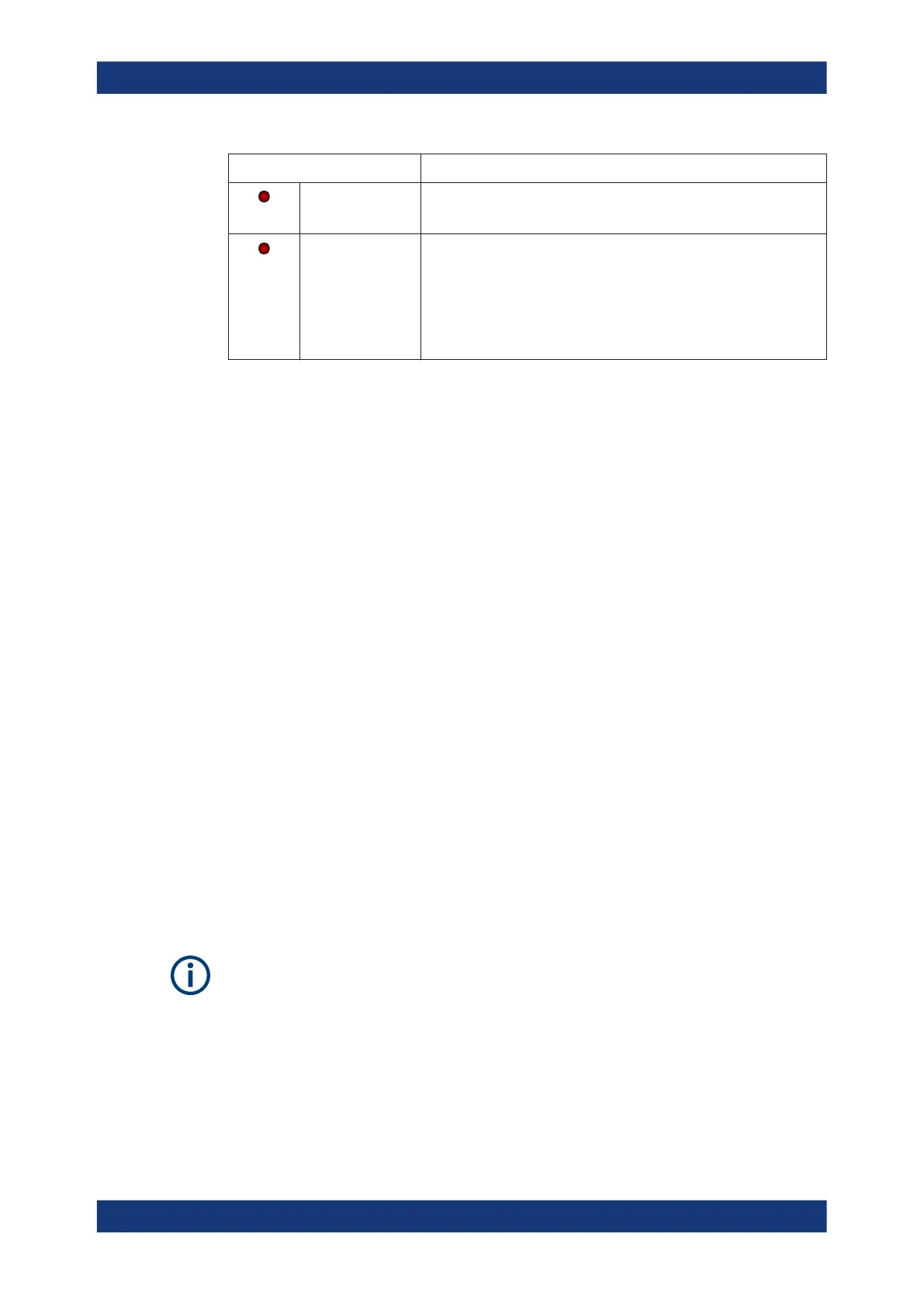
Indication State
Slow flashing red Static error
You can query the error type with SYSTem:SERRor?.
Fast flashing red Critical static error
You can query the error type with SYSTem:SERRor?.
Note: If this state occurs after a firmware update, the update was not
successful. Perform the firmware update again.
See also Chapter 12.3, "Problems during a firmware update",
on page 171.
4.3 Host interface
The host interface is used for establishing a connection between the power sensor and
a USB host. For this purpose, an external cable is needed. See Chapter 3.6, "Connect-
ing a cable to the host interface", on page 17.
4.4 Trigger I/O connector
The trigger I/O is a connector of SMB type.
It is used as an input for signals if the trigger source parameter is set to EXTernal2. It
is used as an output for trigger signals if the sensor is operated in the trigger sender
mode.
Further information:
●
Chapter 9.5.2, "Triggering", on page 75
4.5 LAN PoE interface
Available only for LAN power sensors.
An Ethernet RJ45 connector is used to connect the LAN connector to a local area net-
work (LAN).
Supply the electrical power over the LAN PoE interface. See Chapter 3.5, "Powering
the power sensor", on page 16.
LAN reset button
The LAN reset button is used for resetting the Ethernet connection parameters of the
power sensor to their default values.
LAN PoE interface

 Loading...

