Remote control commands
R&S
®
NRPxxS(N)
116User Manual 1177.5079.02 ─ 15
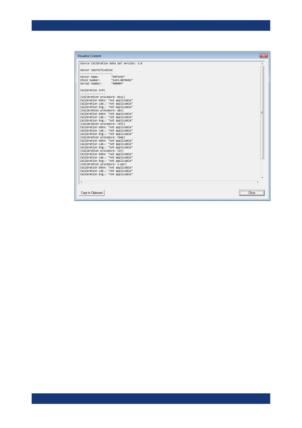
Figure 9-10: Example
Global Flags
Groups the settings for the power sensor behavior regarding S-parameter corrections.
S-Parameter Correction ON by Default ← Global Flags
If this option is enabled, the S-parameter correction is activated automatically when the
sensor is started.
S-Parameter Correction State Locked ← Global Flags
If enabled, the state that is selected with "S-Parameter Correction ON by Default" is
locked and cannot be changed using:
●
[SENSe<Sensor>:]CORRection:SPDevice:STATe
●
R&S NRP2 base unit
S-Parameter Device Locked ← Global Flags
If enabled, the S-parameter device that is selected as the default device in the table of
S-parameter devices is locked and cannot be changed using:
●
[SENSe<Sensor>:]CORRection:SPDevice:SELect
●
R&S NRP2 base unit
The default S-parameter device is the S-parameter device that you have selected
when the power sensor is started.
Configuring basic measurement parameters

 Loading...

