Preparing for use
R&S
®
NRPxxS(N)
18User Manual 1177.5079.02 ─ 15
3.7.1 Computer
If the controlling host is a computer, you can operate the power sensor in several ways.
For details, see Chapter 5, "Operating concepts", on page 31.
► Establish the connection using:
● Host interface
See Chapter 3.7.1.1, "Simple USB connection", on page 18.
See Chapter 3.7.1.2, "R&S NRP‑Z5 sensor hub setup", on page 19.
● LAN interface, if the power sensor is a LAN power sensor
See Chapter 3.7.3, "Using a LAN connection", on page 21.
3.7.1.1 Simple USB connection
All R&S NRPxxS(N) power sensors can be connected to the USB interface of a com-
puter.
Required equipment
●
R&S NRPxxS(N) power sensor
●
R&S NRP‑ZKU cable
Setup
NRP
3-Path Diode Power Sensor
MHz to GHz, 100 pW to 200 mW (−70 dBm to +23 dBm)
SMART SENSOR TECHNOLOGY
1
2
3
4
5
6
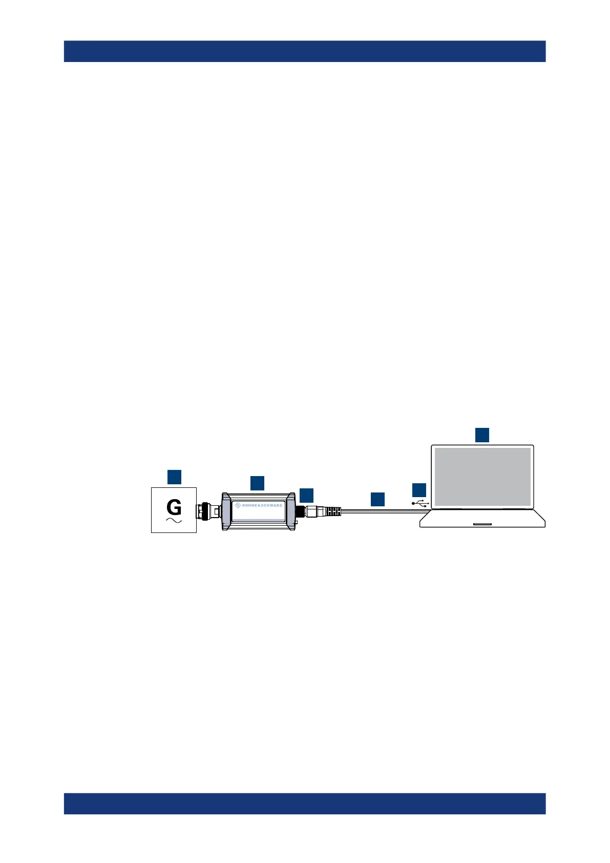
Figure 3-1: Setup with an R&S
NRP
‑
ZKU cable
1 = Signal source
2 = R&S NRPxxS(N) power sensor
3 = Host interface connector
4 = R&S NRP‑ZKU cable
5 = USB connector
6 = Computer with installed VISA driver or R&S NRP Toolkit
Set up as shown in Figure 3-1.
1. Connect the R&S NRP‑ZKU cable to the power sensor. See "To connect a cable to
the host interface of the power sensor" on page 17.
2. Connect the R&S NRP‑ZKU cable to the computer.
3.
NOTICE! Incorrectly connecting or disconnecting the power sensor can damage
the power sensor or lead to erroneous results. Ensure that you connect or discon-
Connecting to a controlling host

 Loading...

