Preparing for use
R&S
®
NRPxxS(N)
21User Manual 1177.5079.02 ─ 15
See Chapter 3.7.3, "Using a LAN connection", on page 21.
3.7.3 Using a LAN connection
Requires a power sensor with networking capabilities, a LAN power sensor.
3.7.3.1 Connecting a LAN power sensor to the LAN
Depending on the available equipment, you can choose from different ways to connect
a LAN power sensor to a controlling host.
The Ethernet interface of a LAN power sensor requires PoE (power over Ethernet).
See Chapter 4.5, "LAN PoE interface", on page 29.
Electromagnetic interference (EMI) can affect the measurement results. To avoid any
impact, use category 5 cables or better.
Setup with a PoE Ethernet switch
3
1
2 4
6
HOST
INTERFACE
IN: 3 V or 5 V logic
OUT: min. 2 V into 50 Ω
max. 5.3 V
TRIG2
I/0
PoE
SMART SENSOR TECHNOLOGY
NRP
5
7
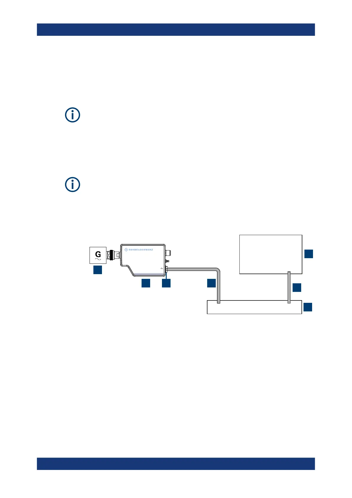
Figure 3-3: Setup with a PoE Ethernet switch
1 = Signal source
2 = LAN power sensor
3 = RJ-45 Ethernet connector
4, 6 = RJ-45 Ethernet cable
5 = Controlling host
7 = Ethernet switch supporting PoE power delivery, e.g. R&S NRP-ZAP1
1.
NOTICE! Incorrectly connecting or disconnecting the power sensor can damage
the power sensor or lead to erroneous results. Ensure that you connect or discon-
nect the power sensor as described in Chapter 3.4, "Connecting to a DUT",
on page 15.
Connect the power sensor to the signal source.
Connecting to a controlling host

 Loading...

