Remote control basics
R&S
®
NRPxxS(N)
160User Manual 1177.5079.02 ─ 15
0
1
2
3
4
5
6
7
8
9
10
11
12
13
14
15
0
Sensor power
0
0
0
Sensor please zero
0
0
0
0
0
0
0
0
0
0
+
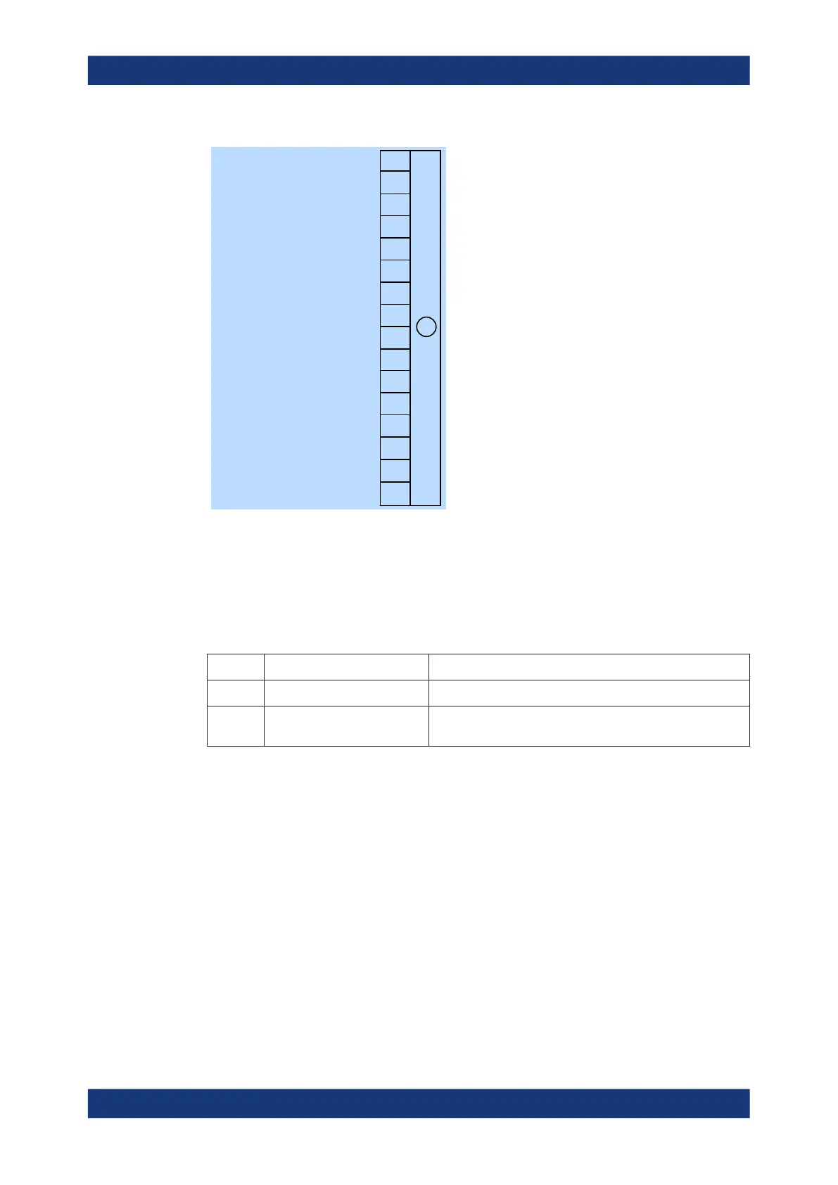
Figure 11-4: Questionable power status register
Querying the register:
●
STATus:QUEStionable:POWer:CONDition?
●
STATus:QUEStionable:POWer[:SUMMary][:EVENt]?
Table 11-6: Used questionable power status bits and their meaning
Bit no. Short description Bit is set if
1 Sensor power Measurement data of the power sensor is corrupt.
5 Sensor please zero Zero correction for the power sensor is no longer correct. Per-
form a zero correction.
11.2.3.2 Questionable calibration status register
Contains information whether the zeroing of the power sensor was successful.
Status reporting system

 Loading...

