Remote control commands
R&S
®
NRPxxS(N)
77User Manual 1177.5079.02 ─ 15
p
t
A B C A
D E F D
1 1 1
2
3
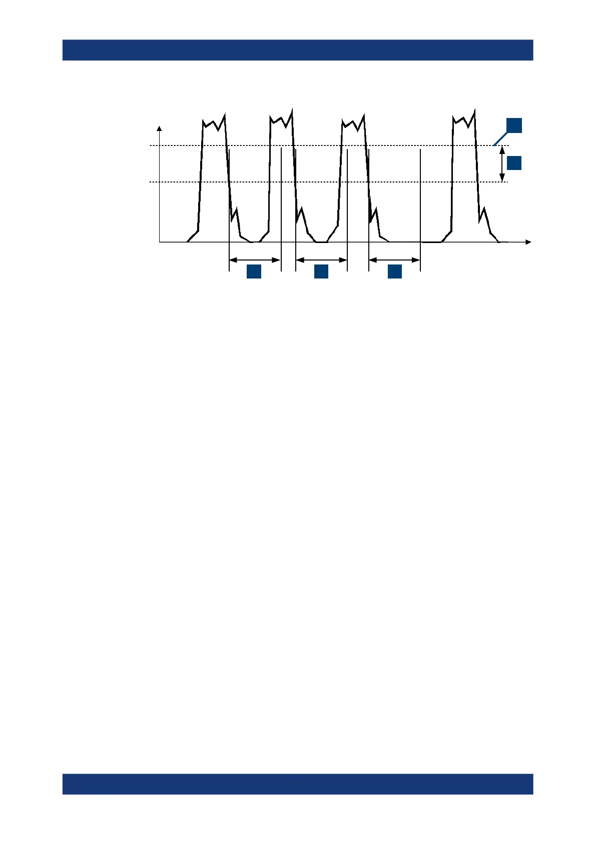
Figure 9-1: Significance of the dropout time
1 = Dropout time
2 = Trigger hysteresis
3 = Trigger level
The RF power between the slots is below the threshold defined by the trigger level and
the trigger hysteresis. Therefore, the trigger hysteresis alone cannot prevent triggering
at B or at C. Therefore, set the dropout time greater than the time elapsed between
points D and B and between E and C, but smaller than the time elapsed between F
and A. Thus, you ensure that triggering takes place at A.
Because the mechanism associated with the dropout time is reactivated whenever the
trigger threshold is crossed, you can obtain also unambiguous triggering for many
complex signals.
If you use a hold-off time instead of a dropout time, you can obtain stable triggering
conditions - regular triggering at the same point. But you cannot achieve exclusive trig-
gering at A.
9.5.2.5 Hold-off time
During the hold-off time, a period after a trigger event, all trigger events are ignored.
Controlling the measurement

 Loading...

