See parameters E1.10 and E1.12.
● 13: Stopped by the external error
This signal is activated when the error "E-St" is generated, and deactivated
when the error is reset. For "E-St", see "External digital input" group.
● 14: Error output
Active when error occurs; inactive when error is reset.
● 15: Reserved
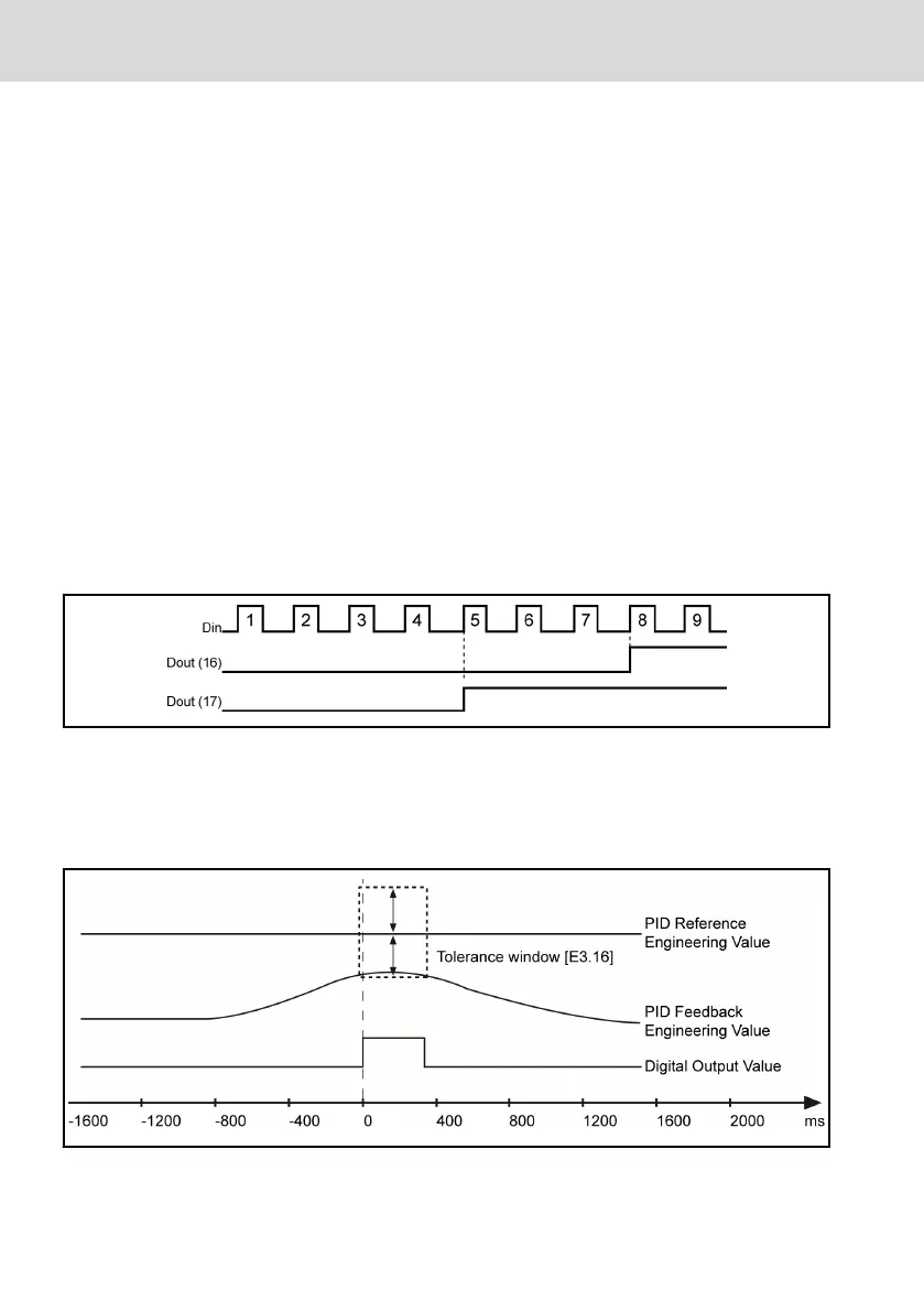
● 16: Target counter value reached
When number of input pulse equals to the setting value defined in E1.14, the
output is active till the next pulse of the input signal after the counter value is
cleared.
● 17: Middle counter value reached
When number of input pulse equals to the value defined in E1.13, the output
is active till the next pulse of the input signal after the counter value is
cleared.
Example: [E1.13]=5, [E1.14]=8, the counter is reset with external terminal
control, the output is described as below:
Fig. 8-39: Middle counter value reached
● 18: PID reference engineering value reached tolerance
When PID feedback engineering value reaches the tolerance window defined
by E3.16, the output is active until the PID feedback engineering value leaves
the window, see the figure below:
Fig. 8-40: Digital output behavior when PID reference engineering value reached
For details of PID regulation, see chapter 8.9 "Group E3: PID Control" on page
111.
Bosch Rexroth AG
Parameter Settings
EFC 3600
100/259
DOK-RCON03-EFC-3600***-IT03-EN-P