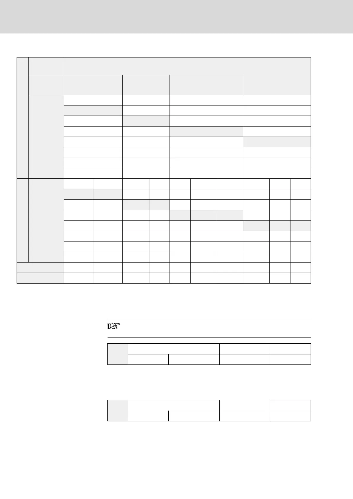
Decimal
Displayed
value
1234
bit
4
th
number
(x 1000 +)
3
rd
number
(x 100 +)
2
nd
number
(x 10 +)
1
st
number
(x 1)
bit value
0 0 0 0
1 1 1 1
2 2 2 2
3 3 3 3
4 4
5 5
6 6
7 7
Binary
bit value
0 0 0 0 0 0 0 0 0 0
0 1 0 1 0 0 1 0 0 1
1 0 1 0 0 1 0 0 1 0
1 1 1 1 0 1 1 0 1 1
1 0 0 1 0 0
1 0 1 1 0 1
1 1 0 1 1 0
1 1 1 1 1 1
Digital input REV FWD X8 X7 X6 X5 X4 X3 X2 X1
Status OPEN CLOSED CLOSED OPEN OPEN CLOSED CLOSED CLOSED OPEN OPEN
Tab. 7-3: Explanation to displayed value of digital inputs status
When [b0.08] or [b0.09] = 17, the monitoring values displayed in the LCD
panel from top to bottom are: output frequency, output current, DC bus volt‐
age, output voltage, output rotation speed and output power.
There are totally 18 status parameters, all of which can be dis‐
played by switching <►►> in either running or stopping mode.
b0.10
Scale factor of user-defined value Factory default 100.0
Setting range 0.1...1,000.0 % Minimum unit 0.1
● Valid only for ‘LCD display value in run mode’ [b0.08] or ‘LCD display
value in stop mode’ [b0.09] = 10 or 11.
● User-defined reference value (User-defined output value) = Set frequen‐
cy (Output frequency) x [b0.10]
b0.11
Parameter filter setting Factory default 0
Setting range 0...3 Minimum unit 1
● Only parameters of the selected groups are visible.
Bosch Rexroth AG DOK-RCON02-FV*********-IB08-EN-P104/259
Rexroth Frequency Converter Fv
Parameter Settings

 Loading...


