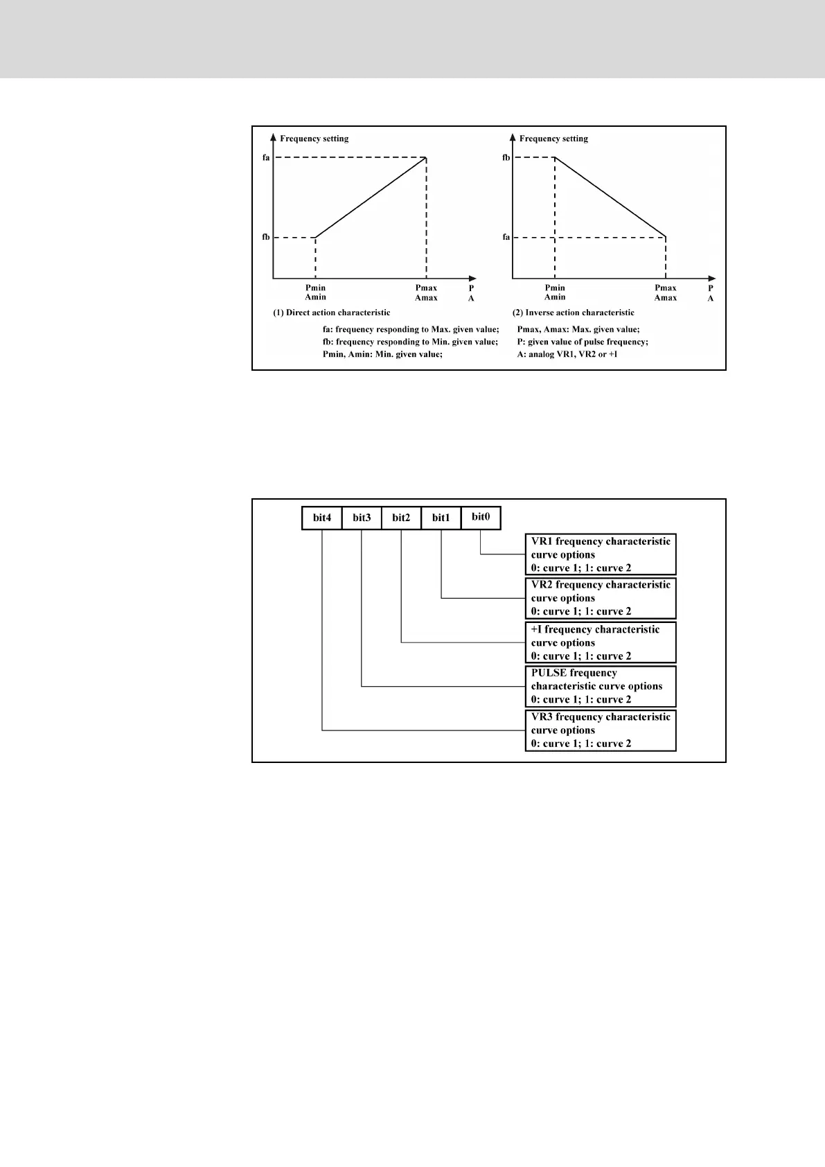
Fig. 7-36: Output frequency characteristics curves
● Analog input A being 100 % corresponds to 10 V or 20 mA, and pulse
frequency P being 100 % corresponds to the maximum input pulse fre‐
quency defined with E0.15.
● Parameter E0.13 is used to select output frequency characteristic
curves for VR1, VR2, VR3, +I and PULSE frequency reference chan‐
nels, as shown in figure below.
Fig. 7-37: Reference frequency curve selection
● Parameter E0.14 is used to define the analog channel filter time con‐
stant for filtering processing of input signals. Longer filter time means
stronger anti-interference capability and slower response; shorter filter‐
ing time means weaker anti-interference capability and faster response.
● Parameter E0.09 is used to select the source of analog reference fre‐
quency. VR2, VR3 and +I inputs are inactive if [E0.09] = 6.
● If [E0.09] = 6, VR1 input inverse frequency characteristic curve is deacti‐
vated.
● If [E0.09] = 6 and the voltage range of VR1 analog input is -10 V...0 V...
+10 V, direction information exists. In this case, the direction control by
operating panel or digital inputs is automatically deactivated, and is not
subject to the rotation direction parameter S3.14, and the dead zone is
determined with E0.24.
Bosch Rexroth AG DOK-RCON02-FV*********-IB08-EN-P138/259
Rexroth Frequency Converter Fv
Parameter Settings
 Loading...


