● The input of PTC / NTC shares the same channel with VR1 or VR2.
Therefore the settings of E4.07 should avoid mutually exclusive settings
as shown below:
– When [E4.07] = 1, if settings are as below,
– [E3.00] = 1 / 3 or [E3.13] = 1
– [E3.00]=1 / 2 or [E3.03] = 2 / 3
– [E0.01]...[E0.08] = 18 / 23 / 28
– [b1.00] = 2 or [E0.09] = 0 / 3 / 4 / 6
– [b1.03] = 2 or [S1.05] = 1
Fv will report fault message "PRSE" after start.
– When [E4.07] = 2, if settings are as below,
– [E3.00] = 1 / 3 or [E3.13] = 2
– [E3.00] = 1 / 2 or [E3.03] = 4 / 5
– [E0.01] to [E0.08] = 24 / 29
– [b1.00] = 2 or [E0.09] = 1 / 3 / 5
Fv will report fault message "PRSE" after start.
– When [E4.07] = 3, if settings are as below,
– [E3.00] = 1 / 3 or [E3.13] = 3
– [E3.00] = 1 / 2 or [E3.03] = 6 / 7
– [b1.00] = 2 or [E0.09] = 7
● Motor overheat protection input channel shares the same filter time con‐
stant E0.14 with the analog input channel.
E4.08
Motor over heat reference Factory default 2.0
Setting range 0.0...10.0 V Minimum unit 0.1
● When the temperature arrives at the set value of E4.08 (motor overheat
reference), the motor will freewheel stop with fault message "M.O.H."
displayed on the operating panel.
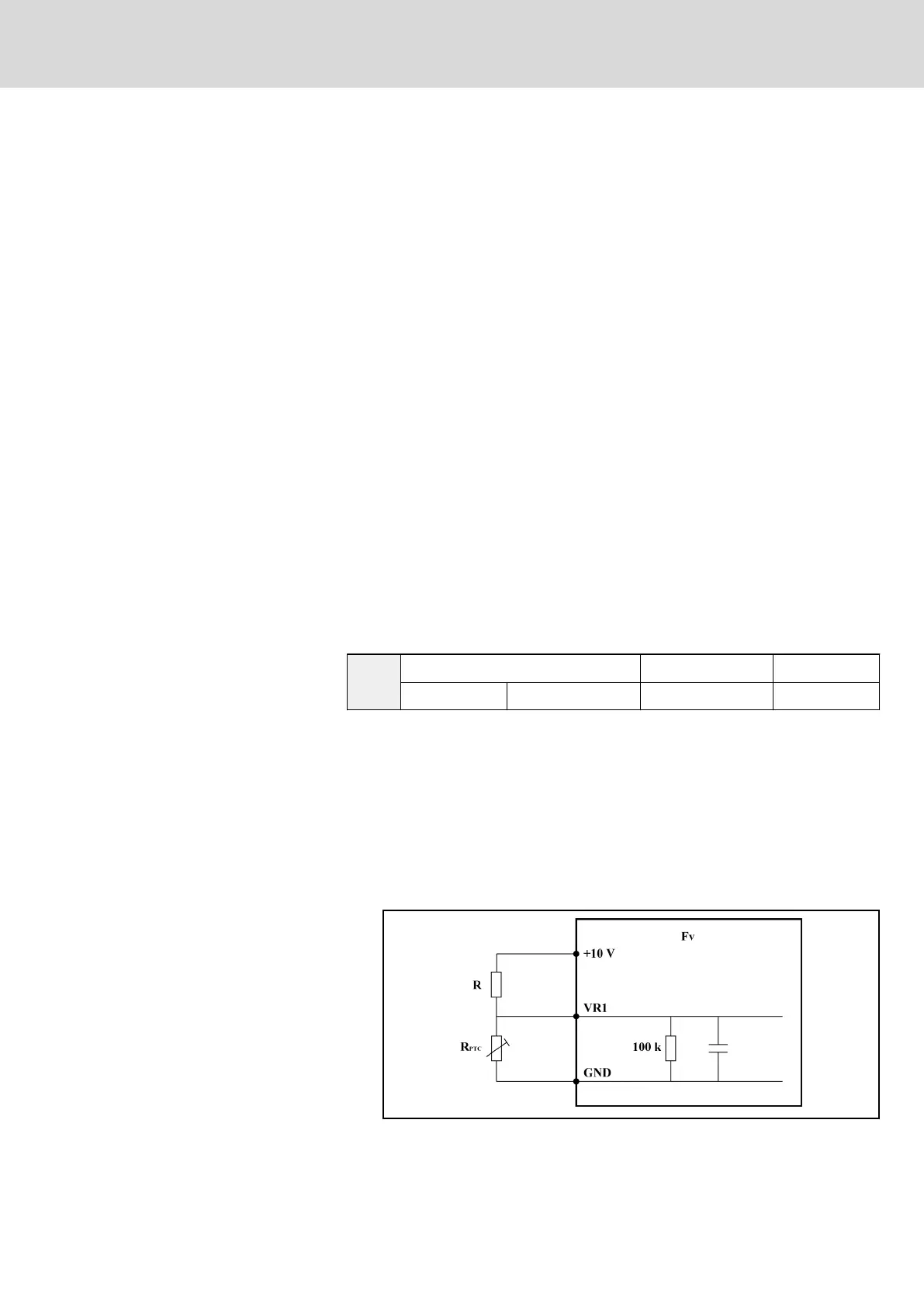
● To activate this function, the corresponding motor over heat reference
based on temperature sensor type needs to be calculated. If [E4.06] =
0, [E4.07] = 1, digital inputs +10 V, VR1 and GND are used.
The calculation formula is shown as below:
[E4.08] = 10 V × (R
PTC
//100 k) / [R + (R
PTC
//100 k)]
The wiring diagram of PTC temperature detection is shown as below:
Fig. 7-50: Wiring diagram of PTC temperature detection
DOK-RCON02-FV*********-IB08-EN-P Bosch Rexroth AG 157/259
Rexroth Frequency Converter Fv
Parameter Settings