Replacement
Adjustment
21 August 2006
Replacement
Adjustment
3-71
PCB
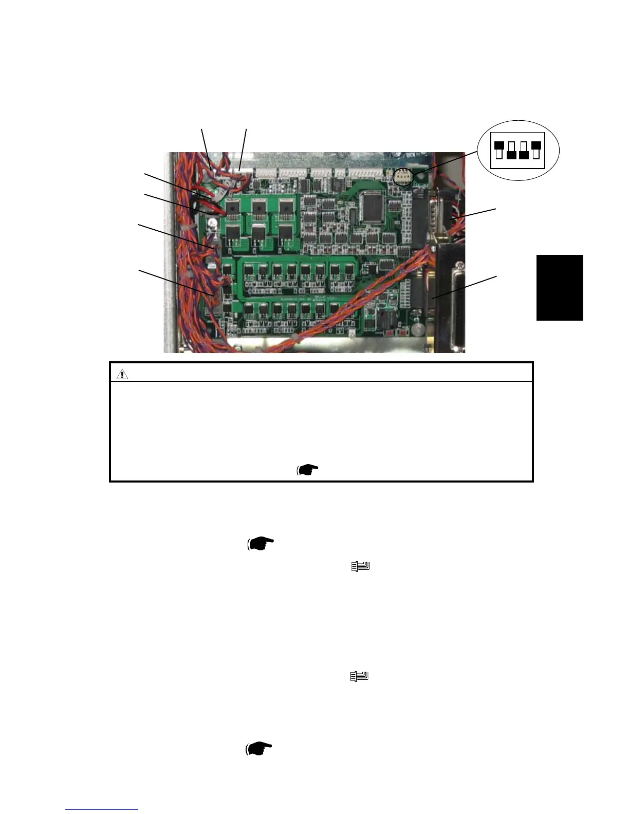
3.7.3 LOWER MD6DC PCB ”C”
C.P5C.P4
C.P12
C.P3
C.P2
C.P13
C.P14
ON
Removal
1. Remove Rear cover (
3.3.1 ).
2. Remove all connectors from the PCB ”C” (
x8 ).
3. Squeeze the barbs of the pins and remove PCB ”C”.
Replacement
1. Reinstall PCB ”C”.
2. Reconnect all connectors to the PCB ”C” (
x8 ).
3. Make sure DIP-switches 1 and 4 is set to ON according to picture.
NOTE: Make sure replaced PCB has matched software with the system, refer-
ring to the latest Technical Bulletin.
4. Reinstall Rear cover (
3.3.1 ).
CAUTION
ESD Hazard! ESD (Electrostatic Discharge) can cause software crashes,
data and/or communications problems. Failure to use proper ESD pro-
cedures will cause damage to electronic components (example: PCBs).
ESD problems can be minimized by maintaining all machine ground con-
nections, ensuring the proper handling of circuit boards and sensors. Use
ESD protection when working near PCBs. Failure to use ESD protection is
likely to result in a PCB failure ( 3.1 ).
C.P11