Section04ENGINEMANAGEMENT(15034-TEC)
Subsection 03 (COMPONENT INSPECTION, REPLACEMENT AND ADJUSTMENT)
Connect one test probe to the WHITE/GREY wire
and the other test probe to the switch top ter-
minal. Measure resistance, it must be close to
0ohm.
Connect one test probe to the BLACK wire and
the other test probe to the switch ring. Measure
resistance, it must be close to 0 ohm.
Safety Lanyard on Switch
Connect test probes to switch BLACK and
BLACK/YELLOW wires. Measure resistance,
it must be close to 0 ohm.
ECM AND MPEM
General
Prior to replacing a suspected ECM or MPEM, en-
sure that all the recommendations in the general
introduction of this section have been followed.
IMPORTANT: When the ECM is replaced, the
Closed Throttle and Idle Actuator must be re-
set. Refer to its specific section for adjustment.
To allow transferring the previous recorded infor-
mation from the old ECM or MPEM to the new
one, use the vehicle communication kit (VCK)
with the B.U.D.S. software. Use Replace ECM
or MPEM in the Module menu. Follows instruc-
tions in its help system.
NOTE: If the old ECM or MPEM is working, it
must be read inside B.U.D.S. prior to removing it
from the vehicle to carry vehicle information and
history to the new ECM or MPEM. Otherwise, per-
form the operations described in IF THE PREVI-
OUS MPEM WAS NOT READ with B.U.D.S. be-
low.
ECM Replacement
CAUTION: Never try to use a 4-TEC Super-
charged ECM on a naturally-aspirated engine.
Doing so will automatically lead to a misfunc-
tion of the Engine Management System (EMS)
and will cause irregular combustion which
will damage the engine. Always make sure to
replace the ECM by an appropriate unit.
Disconnect battery cables.
WARNING
Battery BLACK negative cable must always be
disconnected first and connected last.
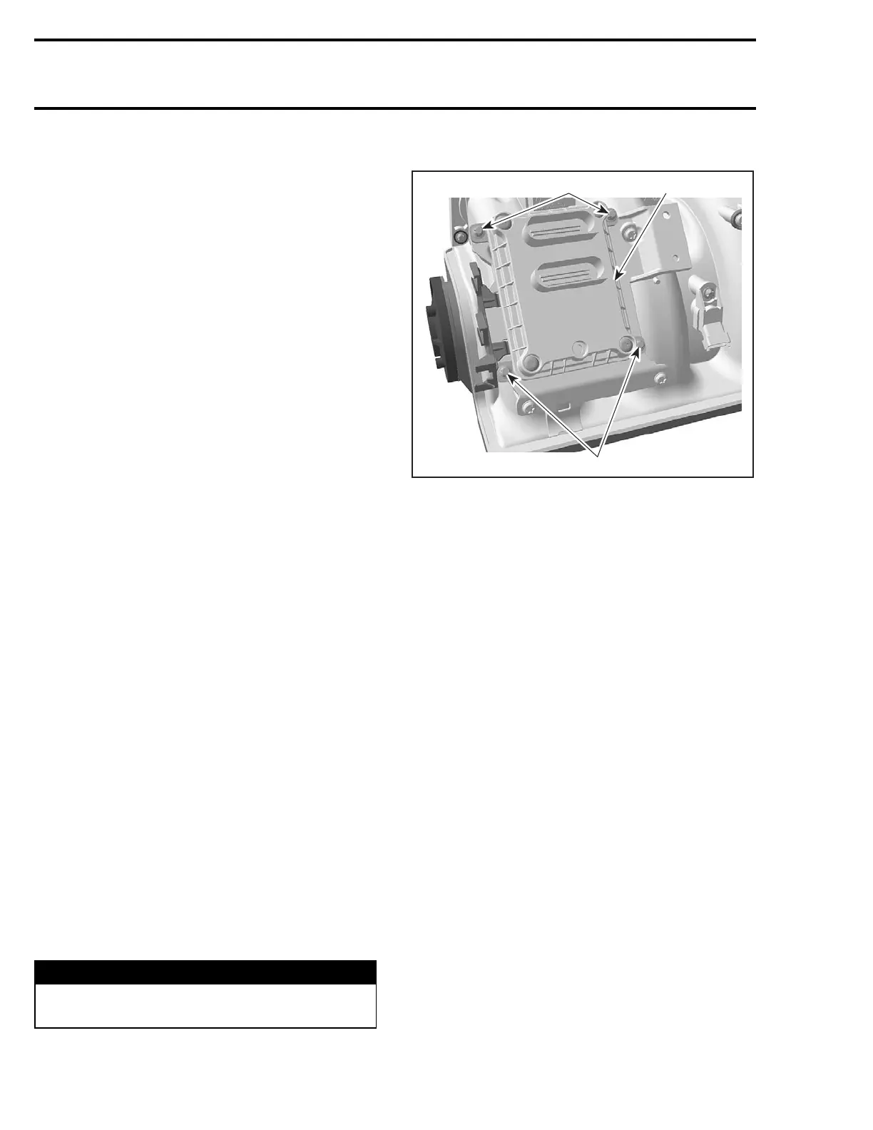
Disconnect both ECM connectors from ECM.
2
2
R1503motr180A
1
TYPICAL
1. ECM
2. Retaining screws
Unscrew all retaining screws and remove the en-
gine ECM from intake manifold.
CAUTION: If ever ECM is replaced, replace it by
the same part or by an approved equivalent.
Install the new ECM to the engine.
Reconnect ECM connectors to ECM then battery
cables.
If the previous ECM was read with B.U.D.S.
Transfer the data from the previous ECM to the
new one using B.U.D.S. then proceed with the
required resets.
Continue procedure as per FINALIZING ECM RE-
PLACEMENT below.
If the previous ECM was NOT read
with B.U.D.S.
– Enter the old ECM serial number in the Part
Replacement under History tab. Click on Add
part in History.
– Reprogram safety lanyard(s).
NOTE: The ECM serial number can be found on
the ECM sticker that also shows the P/N.
Continue procedure as per FINALIZING ECM RE-
PLACEMENT below.
112 smr2005-013

 Loading...


