Section 08 STEERING SYSTEM
Subsection 01 (STEERING SYSTEM)
F07K0UA
1
1
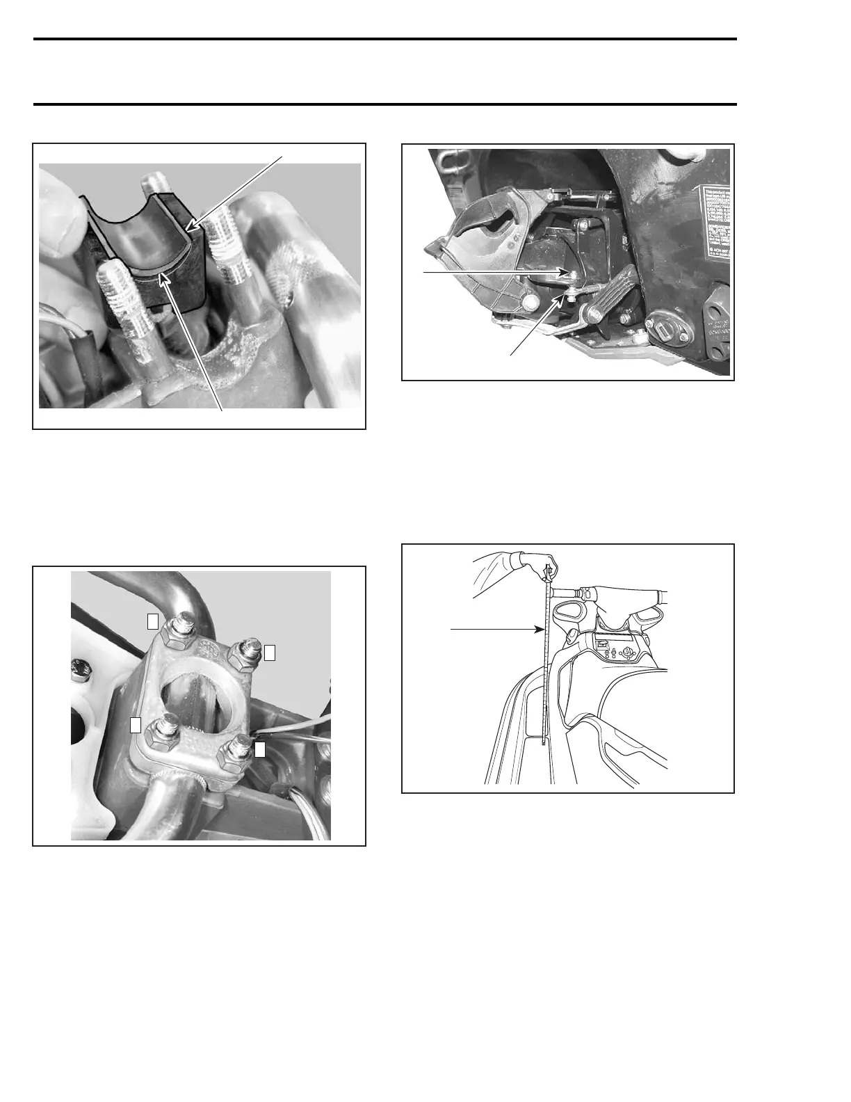
1. Pad must not exceed stopper
All Models
Position handlebar no. 9. Install steering clamp
no. 25 and secure with new elastic stop nuts M8.
Torque nuts to 26 N•m(19lbf•ft) as per the fol-
lowing sequence.
F07K0VA
1
3
2
4
TORQUE SEQUENCE
Ball Joint
Secure the steering cable ball joint no. 44 to the
nozzle as per following illustration.
CAUTION: Ensure the ball joint is parallel
(± 10°) to the nozzle arm.
1
F19J0CA
2
TYPICAL
1. Ball joint below steering arm
2. Torque nut to 7 N•m(62lbf•
in)
ALIGNMENT
Position handlebar in straight ahead position by
measuring each side the distance from handlebar
grip end to floorboard.
F01K07A
1
TYPICAL
1. Measuring handlebar grip end/floorboard distance
Check jet pump nozzle position by placing a
straight edge on nozzle outer end. Measure the
distance on each side of the straight edge. It
must be equalled.
236 smr2005-022
 Loading...


